|
<< Click to Display Table of Contents >> Test Projects |
  
|
|
<< Click to Display Table of Contents >> Test Projects |
|
This chapter describes the setup of the test projects to familiarize yourself with PlantSpecDriven.
All project have the same setup in regards to the enabled features of PlantSpecDriven.
Available projects are:
1.PSD ISO Metric
This project is using the ISO standard template with metric sizes and metric dimensions.
2.PSD ISO Mixed-Metric
This project is using the ISO standard template with imperial sizes and metric dimensions.
3.PSD ISA Imperial
This project is using the ISA standard template with imperial sizes and imperial dimensions.
We also created a drawing which contains the flange and tee symbols for the various standard used by Plant 3D.
The next sections detail what has been adapted for the test projects. Since they are identical in regard to the setup, the ISO Metric project is used for the images.
For a deeper dive into why things are setup the way they are setup in the test project can be read under Configuration.
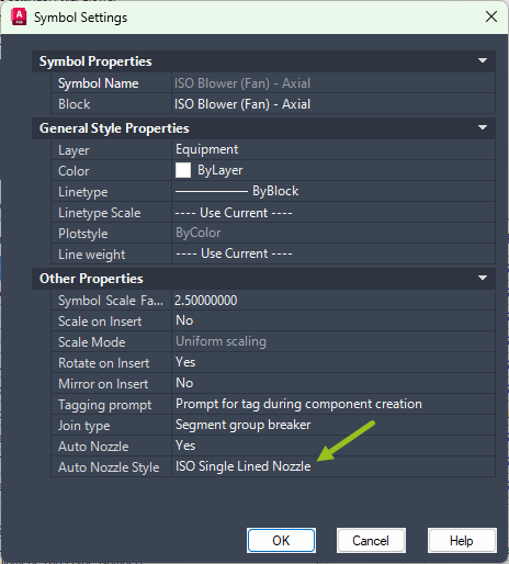
The Auto Nozzle Style has been set to ISO Single Lined Nozzle in order to get a flanged nozzle when connecting with a line segment to an equipment so PlantSpecDriven can automatically insert a default flange symbol.
|
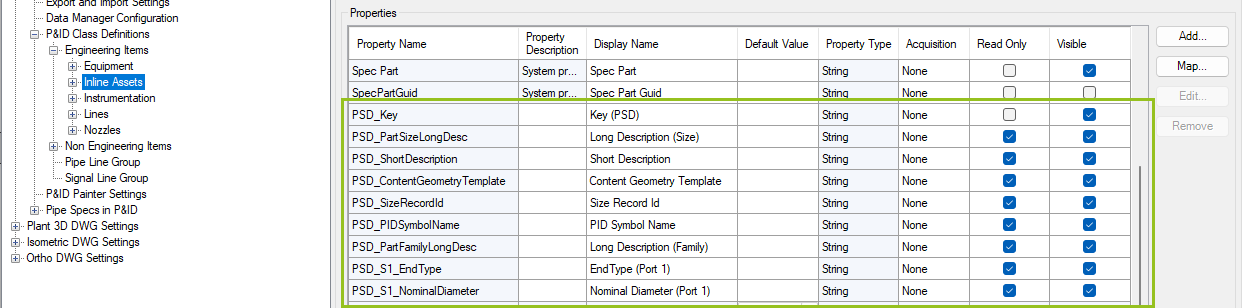
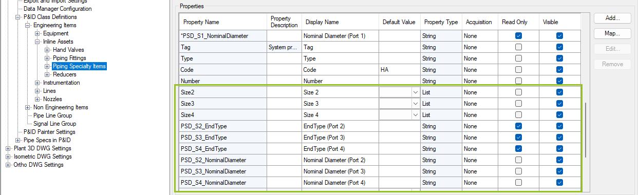
These are the added properties under the Inline Assets class.
|
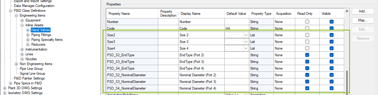
These are the added properties under the Hand Valves class.
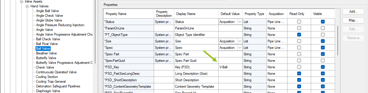
For some specific classes we defined a Key which we also used in the Pipe Specs further down in this chapter.
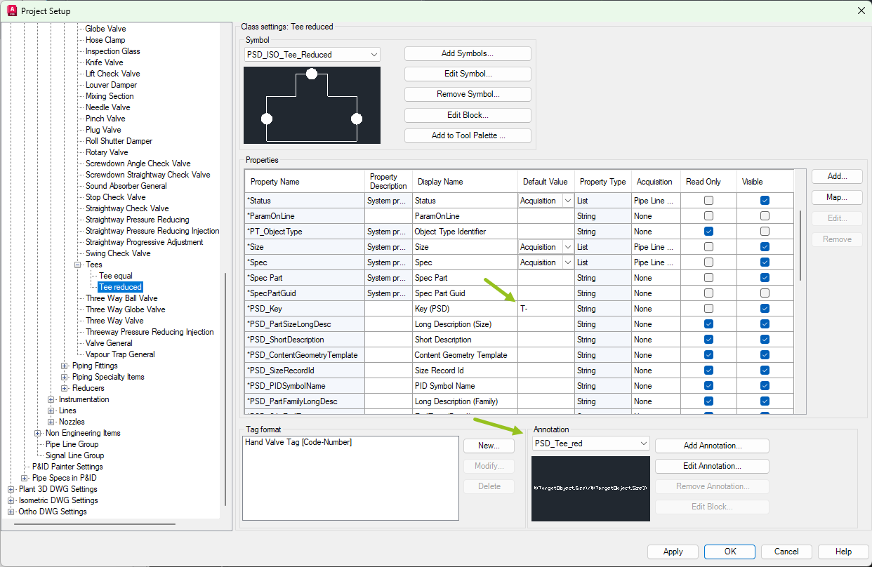
|
Unfortunately the Tees must be under the Hand Valves class, because only the Hand Valves class supports the EndCode option for the AttachmentPoints in the symbols's block. Otherwise we would place the tees under the Piping Fittings class as well. For both tees we use the same Key, because when PlantSpecDriven tries to find the correct tee it'll considers all three sizes and therefore will find either a straight tee or a reduced tee. However, there are different annotations for the straight and reduced tee to show either one size or the sizes of the main line and the branch.
|
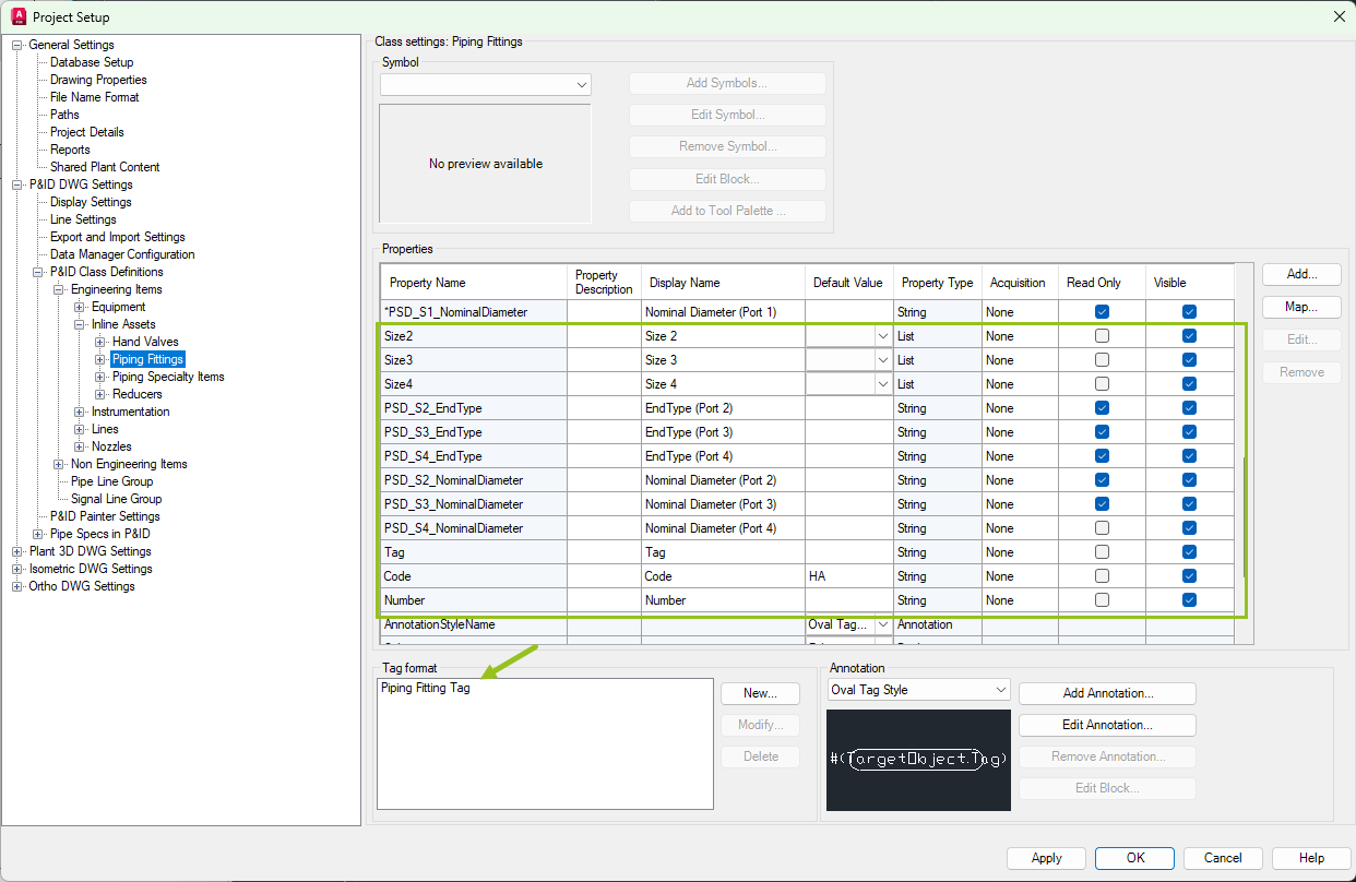
These are the added properties under the Piping Fittings class. This includes properties for the Tag. This is not mandatory, but it makes it easier to identify the piping fittings later in the PlantSpecDriven tree.
|
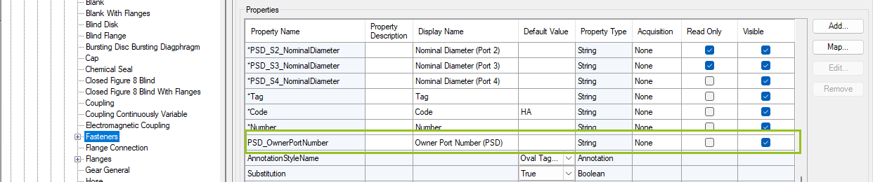
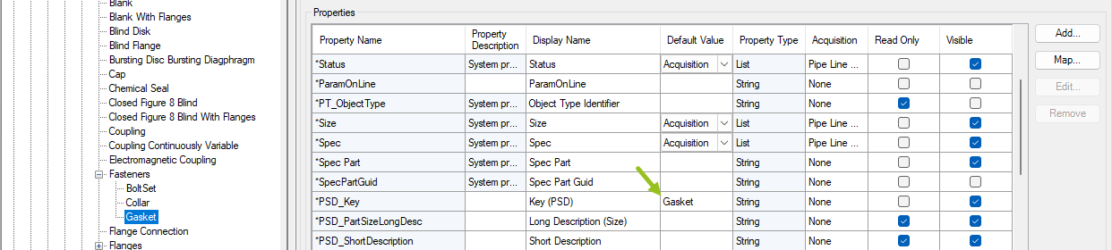
This is the added property under the Fasteners class.
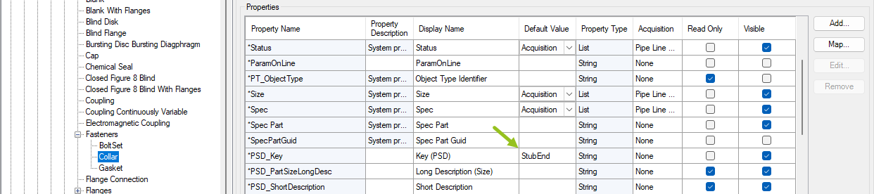
There also Keys set for the BoltSets class (not shown as an image), the Collar,...
...and the Gaskets.
|
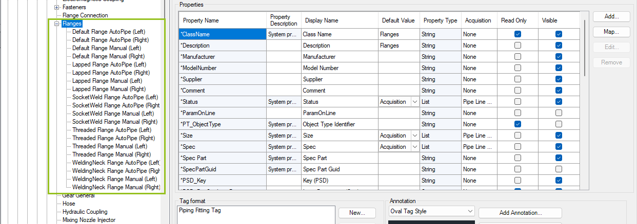
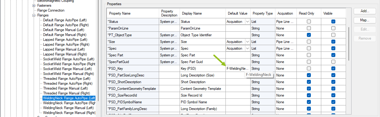
These are the added classes under the Flanges class.
The individual classes have a specific Key set.
|
![]() Piping Specialty Items class (P&ID)
Piping Specialty Items class (P&ID)
These are the added properties under the Piping Fittings class.
|
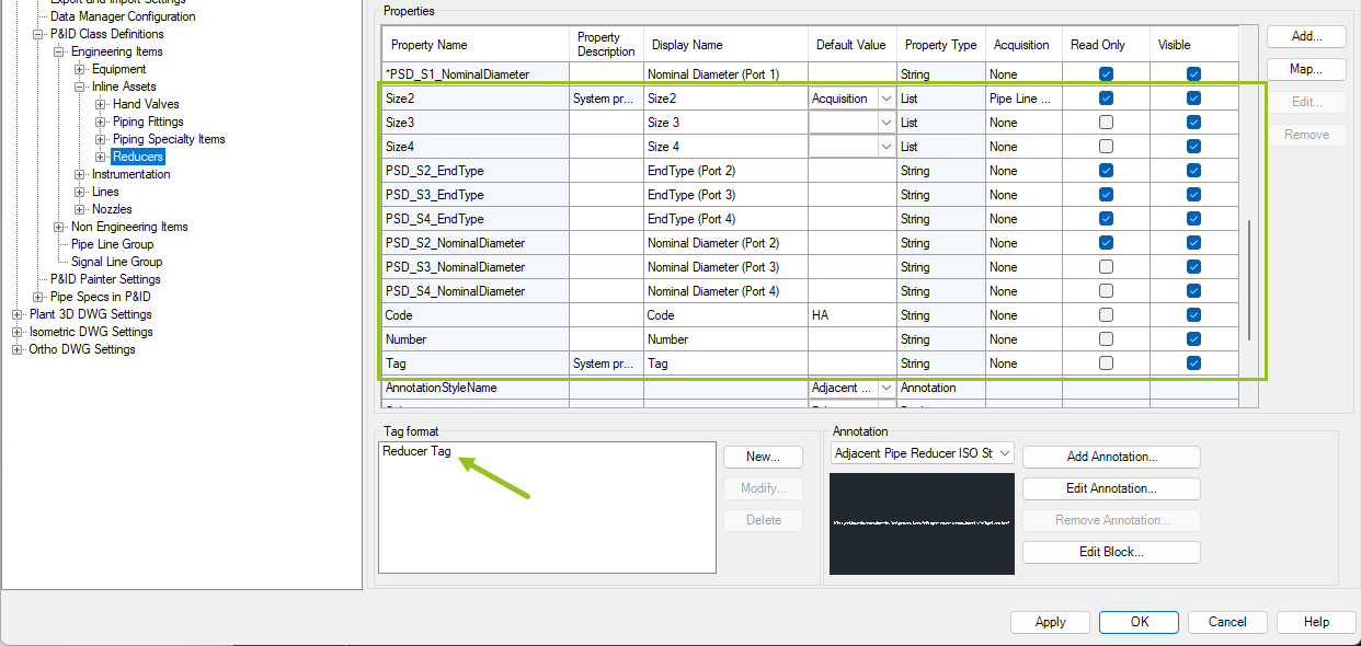
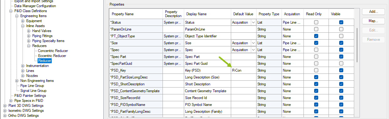
These are the added properties under the Reducers class. Here you will find a Tag as well for convenience.
The Eccentric and Reducer class have specific Keys set.
|
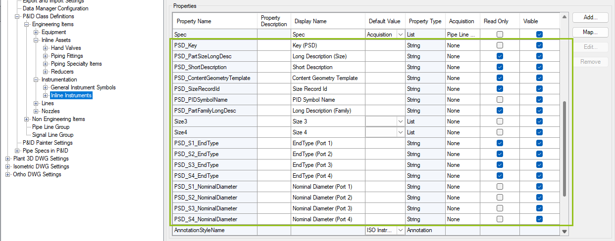
![]() Inline Instruments class (P&ID)
Inline Instruments class (P&ID)
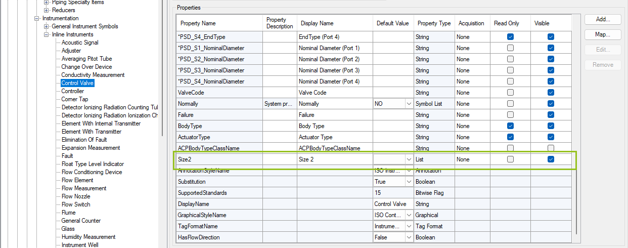
These are the added properties under the Inline Instruments class. Size2 is missing, because this property already exists under Relief Valves class and therefore cannot be created under Inline Instruments again.
Because of that Size2 is created for ALL sub classes under Inline Instruments except the Relief Valves class.
|
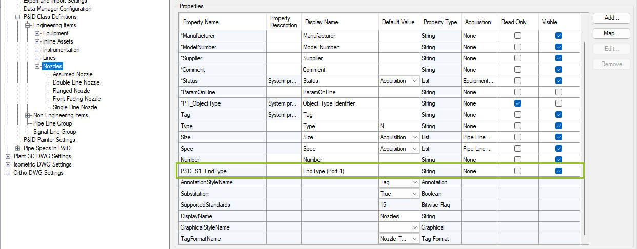
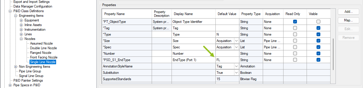
This is the added property under the Nozzles class.
For the EndType we set FL to later get the default flange symbol automatically.
|
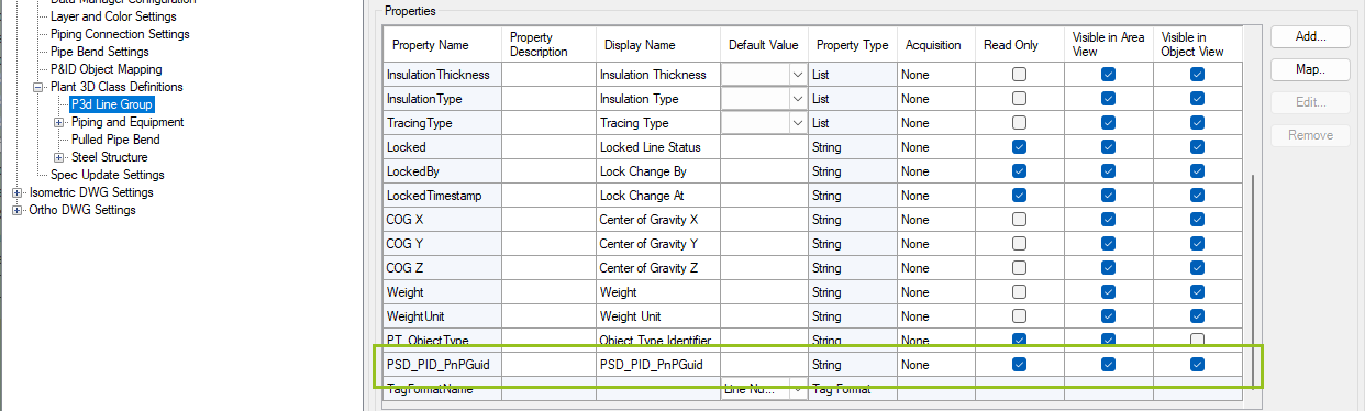
This is the added property under the P3D Line Group class to store the PnPGuid of the P&ID Object.
|
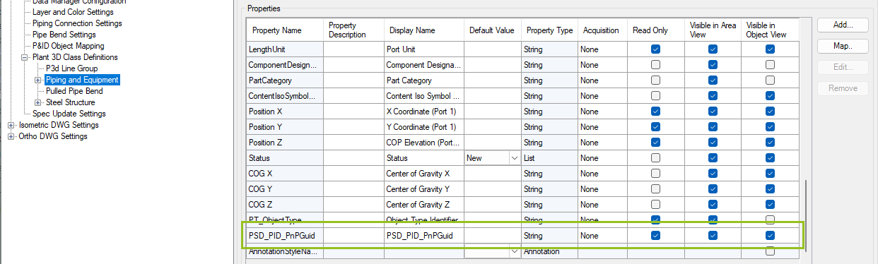
![]() Piping and Equipment class (3D)
Piping and Equipment class (3D)
This is the added property under the Piping and Equipment class to store the PnPGuid of the P&ID Object.
|
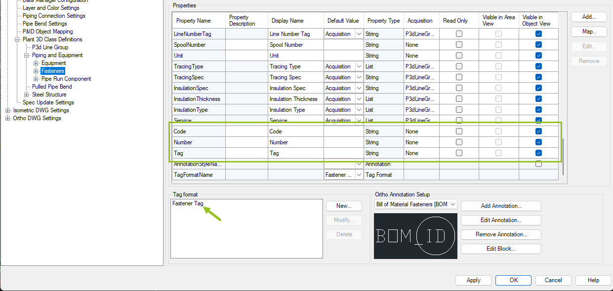
These are the added properties under the Fasteners class for constructing the Tag Format.
|
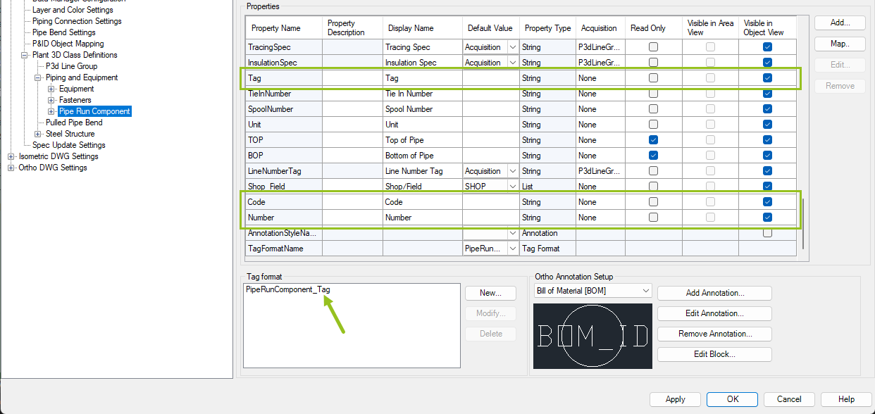
These are the added properties under the Pipe Run Component class for constructing the Tag Format. The Tag property was removed from the Valve class in order to create it again under Pipe Run Component class.
|
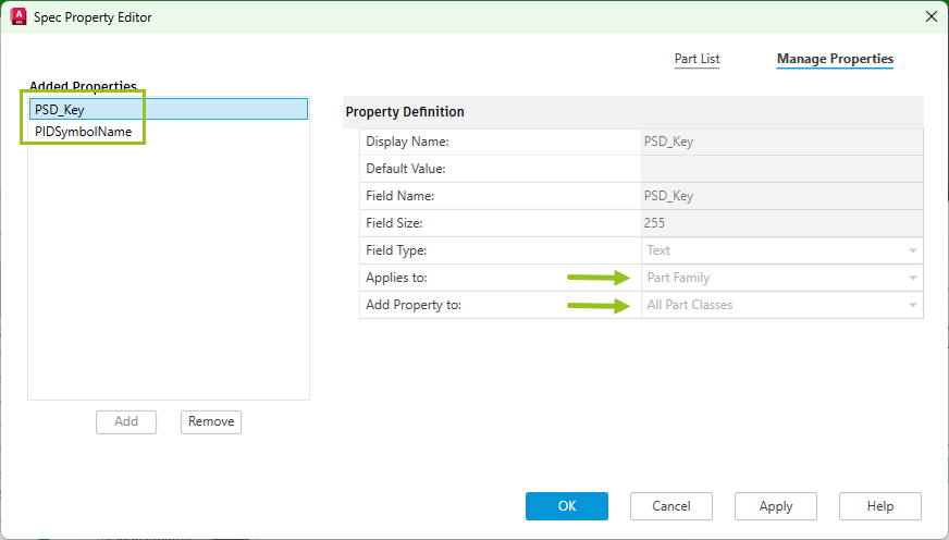
The test project contains a metric (10HC01) and imperial (CS150) pipe spec. In those pipe specs twp additional properties have been created for all Part Classes as a Part Family property.
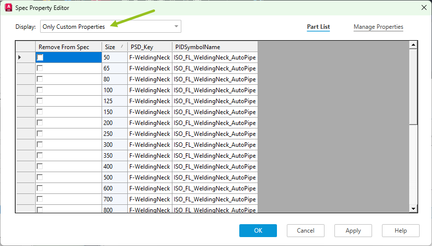
If you edit the parts in the Spec Editor and you switch to view only the Custom Properties you will see filled out properties. Not all parts have the properties filled out. Only those which are relevant for P&ID (i.e. BoltSets, Flanges, Stub Ends, Gaskets, Reducers, Tees, Valves).
|
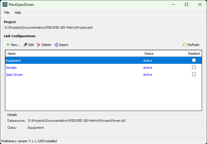
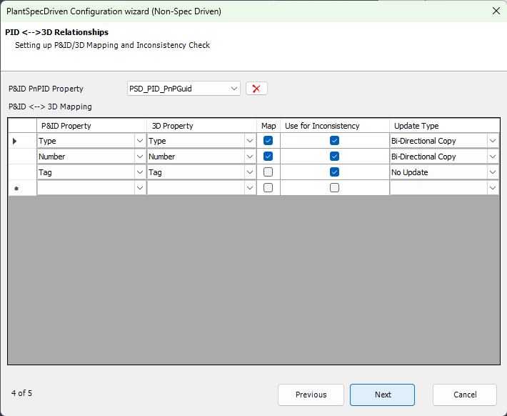
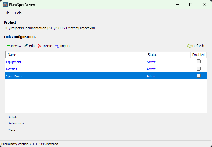
![]() The PlantSpecDriven Wizard Setup - Equipment
The PlantSpecDriven Wizard Setup - Equipment
There is a PlantSpecDriven configuration for Equipment in order to link P&ID and 3D Equipment.
Here the PSD_PID_PnPGuid property from the 3D Equipment class is selected and three properties.
|
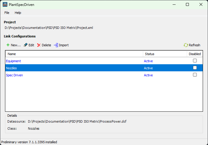
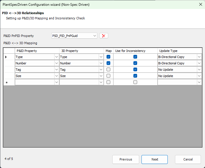
![]() The PlantSpecDriven Wizard Setup - Nozzles
The PlantSpecDriven Wizard Setup - Nozzles
There is a PlantSpecDriven configuration for Nozzle in order to link P&ID and 3D Nozzles.
Here the PSD_PID_PnPGuid property from the 3D Pipe Run Component class is selected and four properties. With the Size property you have a check if the size of a nozzle in P&ID and 3D matches.
|
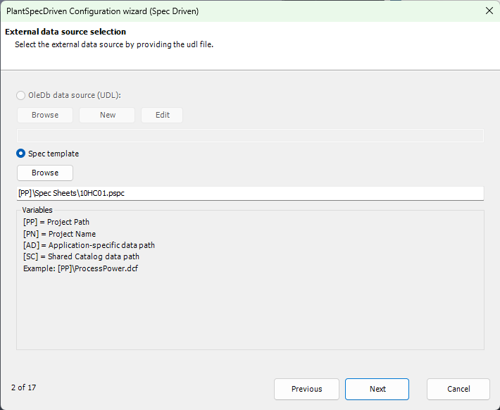
![]() The PlantSpecDriven Wizard Setup - Lines and Assets
The PlantSpecDriven Wizard Setup - Lines and Assets
There is a PlantSpecDriven configuration for the line groups, line segments, Inline Assets, and Inline Instruments.
We selected one of the pipe specs from the project.
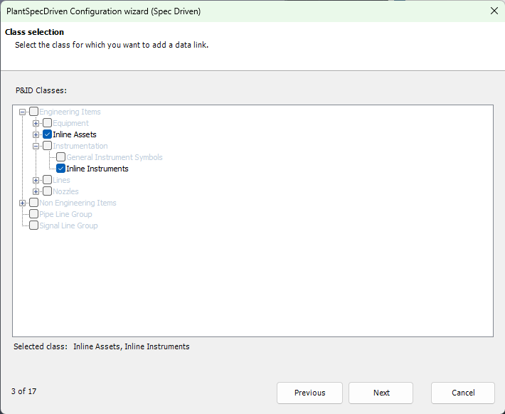
Inline Assets and Inline Instruments will be considered.
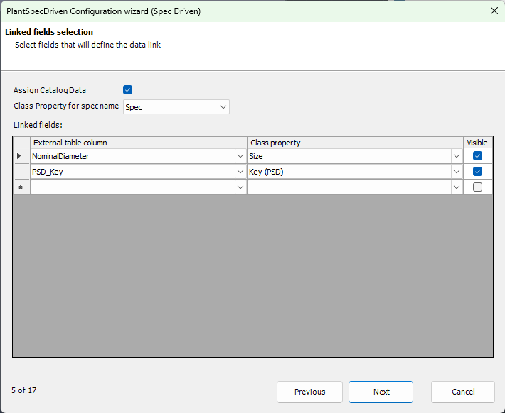
In addition to the spec and size property we added the Key property to filter the pipe specs for suitable parts.
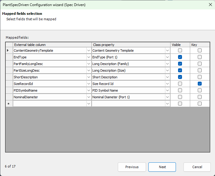
These are the properties we map from the pipe spec to the P&ID properties.
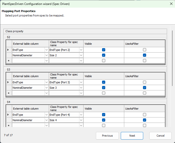
Here we selected more port properties in order to also filter for size 2 - 4.
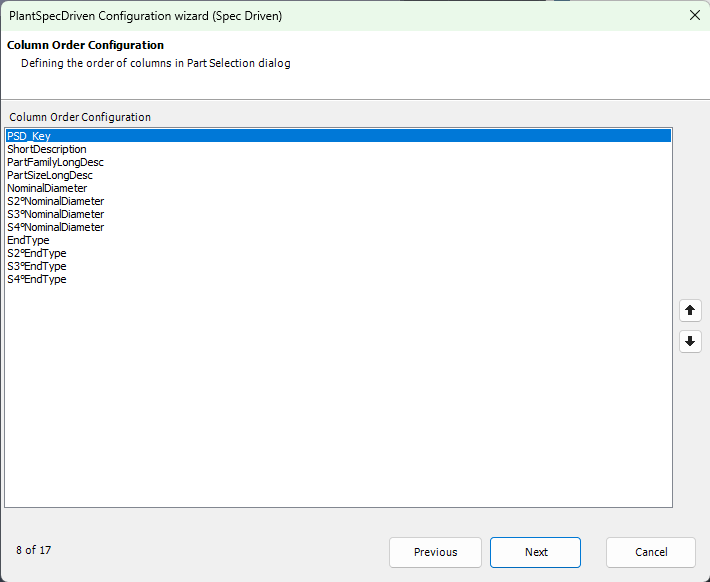
This is the order we defined when selecting a part from the pipe spec in the Assign Catalog Data dialog when inserting a P&ID Symbol.
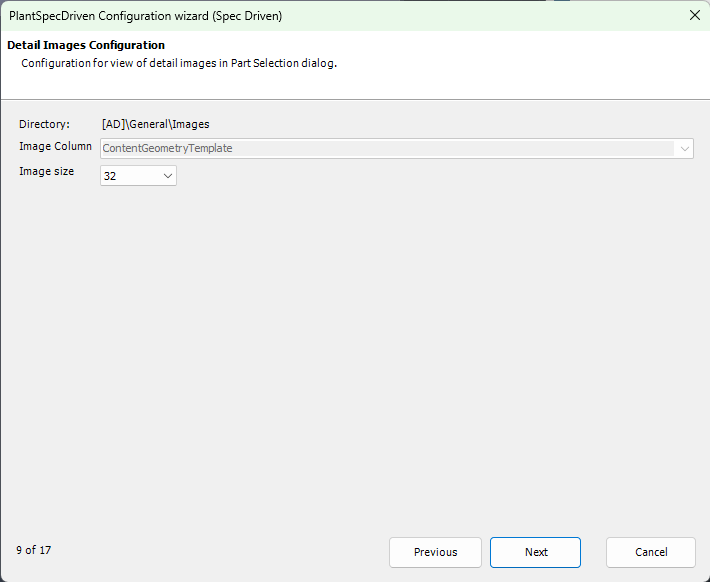
Because we mapped the script name of the 3D part in a property, we can later see the image of the 3D part in
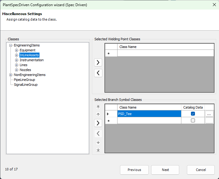
The tees are set as well.
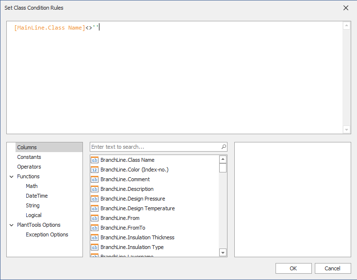
We have to define an expression in order to get the tees inserted automatically with the AutoPipe function. The following statement should always be true.
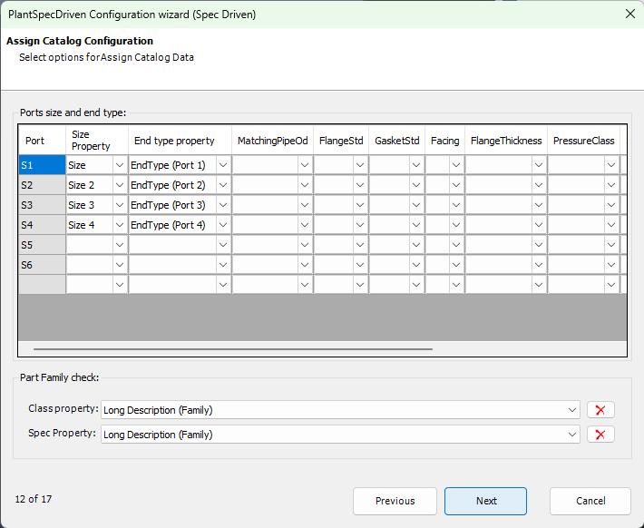
Here we selected the port properties for size and end type. As well as the Part Family Long Description.
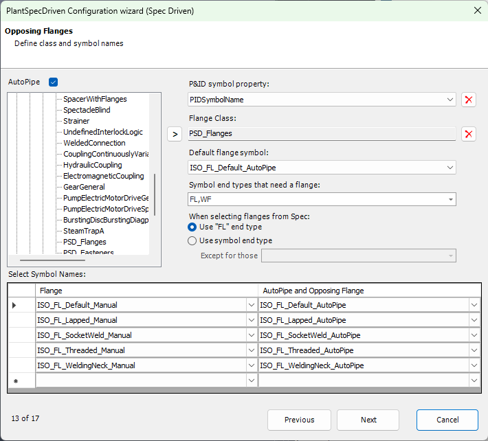
Here we have the settings for AutoPipe to get the flanges.
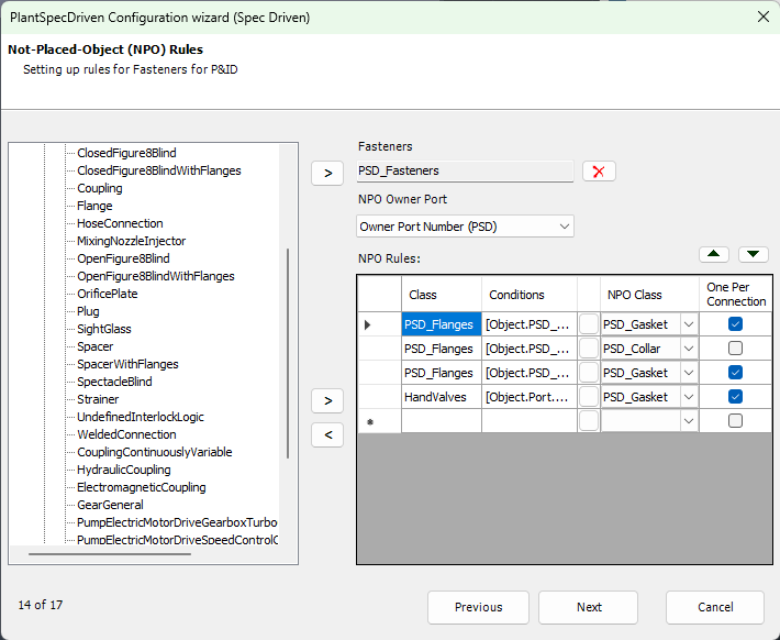
And the settings to get the Fasteners.
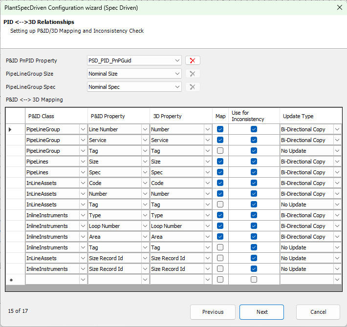
Here we have the mapping between P&ID and 3D.
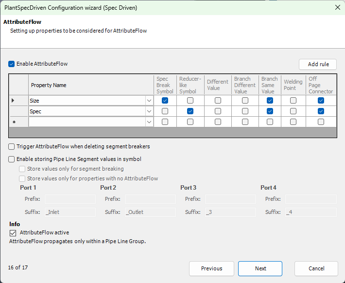
And finally the settings for the AttributeFlow which are the default settings out-of-the-box.
|
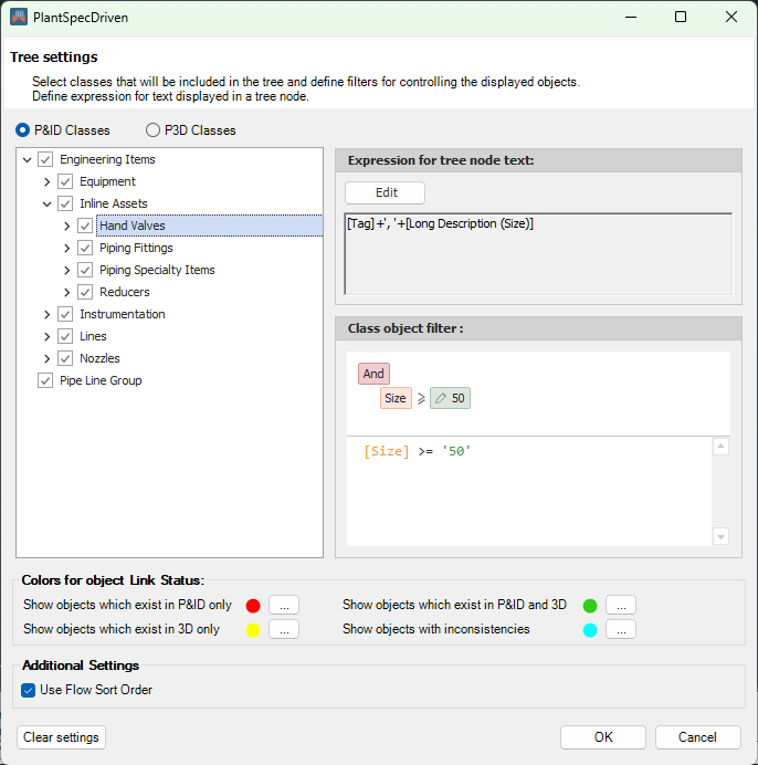
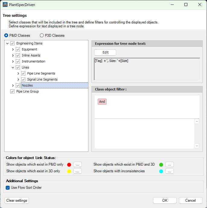
![]() The PlantSpecDriven Tree Settings
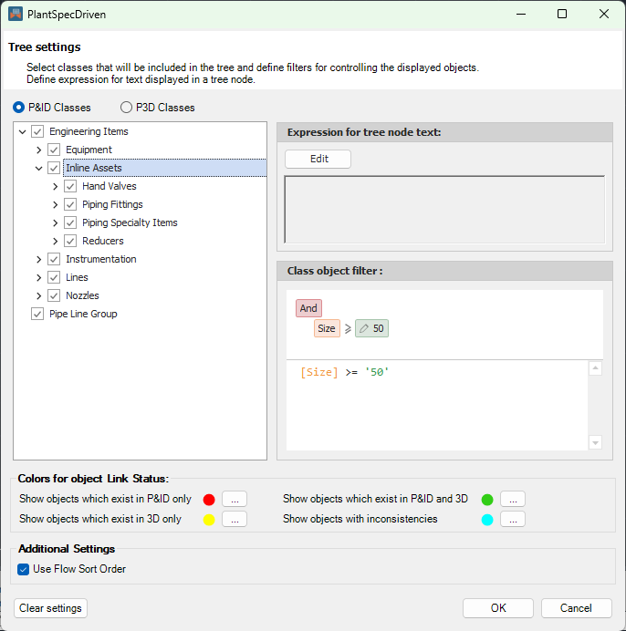
The PlantSpecDriven Tree Settings
For the Inline Instruments class we set the filter to show only the Inline Assets which have a size greater or equal than 50. If you use this setup on a mixed-metric or imperial project, then the filter will automatically applied to 2".
For the Hand Valves class we defined a tree node expression.
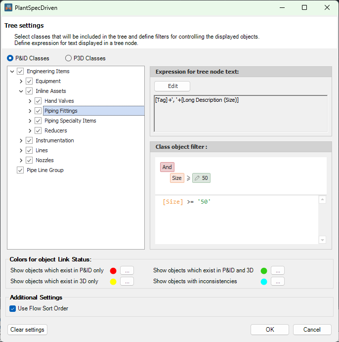
The same for Piping Fittings class.
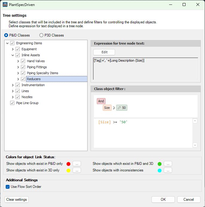
And the Reducers class. The reason why this couldn't be defined for the Inline Assets class is, that the Inline Assets don't have the Tag property.
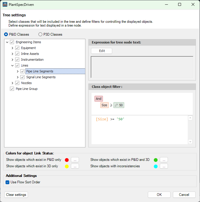
The Pipe Line Segments class will be filtered too.
And for the Nozzles we set the Tree Node expression to show the Tag and the Size.
|
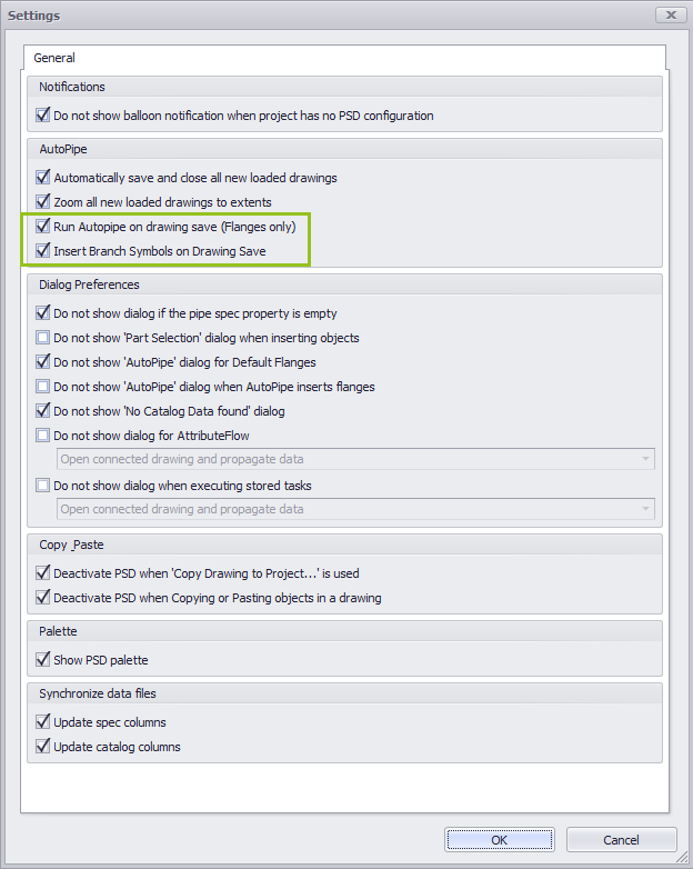
In PlantSpecDriven Settings we enabled the two check boxes related to AutoPipe.
|
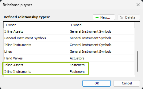
In order for PlantSpecDriven to add the Fasteners under the Inline Assets or Inline Instruments in the structure tree in PlantSpecDriven.
|
Remark: These Videos are not up-to-date and will be revised at a later point.