|
<< Click to Display Table of Contents >> Usage |
  
|
|
<< Click to Display Table of Contents >> Usage |
|
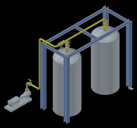
The example used in this chapter looks like this:
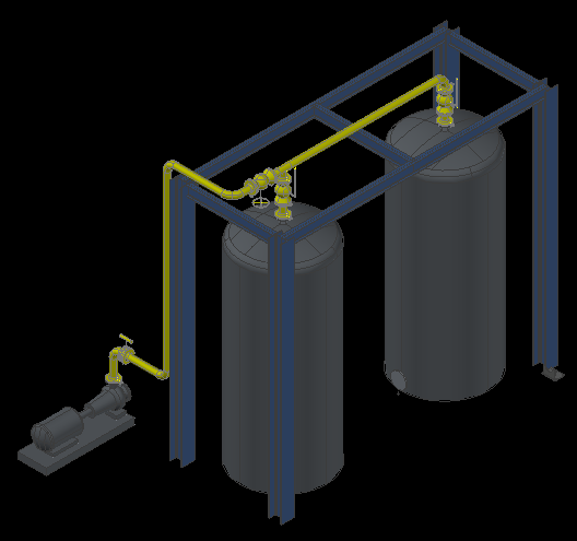
The pump, the two tanks and the structural steel are xrefed into the main "3D 001" drawing.
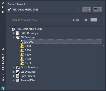
This is how it looks in PlantProjectManager.
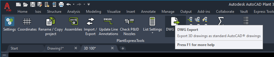
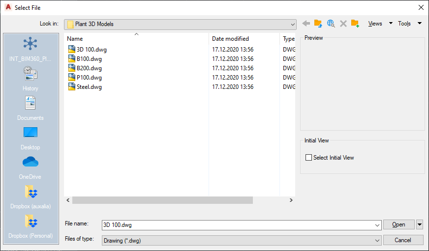
To start the DWG Export you click on the button in the
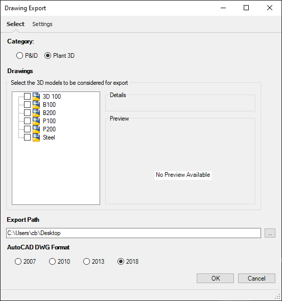
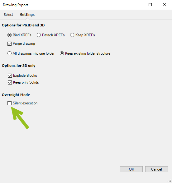
The dialog for the DWG Export function opens up.
There are two tabs. "Select" and "Settings". Under select you can decide if you want to export 3D drawings or P&ID drawings. The process is the same, although P&ID don't have all the options available in the settings.
Under "Export Path" you define the path under which a folder with the drawings will be created.
With AutoCAD DWG Format you can decide which DWG Format should be the result.
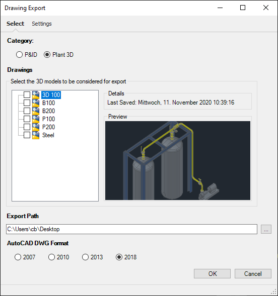
If you click on a drawing node you get the thumbnail preview of the drawing.
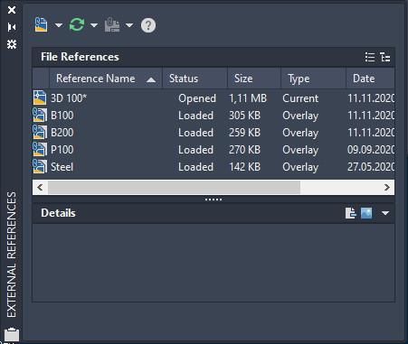
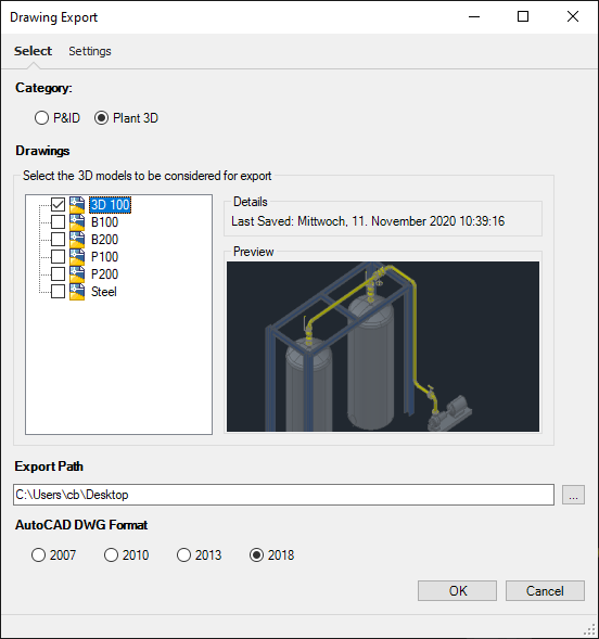
You check the drawing(s) you want to export. You don't need to check the xrefed drawings, because they will be included during the export anyway.
The settings are covered under DWG Export. However, the Settings tab has an additional settings "Silent execution". This will not be stored. The effect is, that if checked, any messages from the DWG Export function will be suppressed to allow an unattended export. This is especially important for bigger projects.
However, there can still be dialogs popping up from Plant 3D. For example, issues with the XREF insertion point. These messages can be suppressed when they appear and then they typically stay closed and won't pop up anymore.
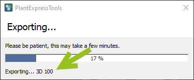
After clicking on the OK button the export begins. You will see a progress bar with a text line under it to give an idea where things are.
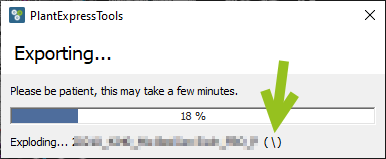
One of the most time consuming parts of the export is the explosion of the blocks.
Therefore, we put a sort of rotational symbol at the end of the text.
You will see:
( \ )
( | )
( / )
( - )
This rotating symbols tells you that the routine is still working.
At the end you get this dialog.
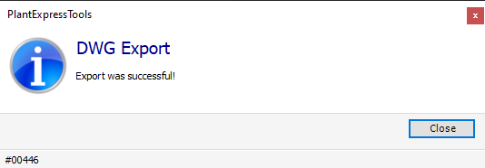
Under the selected path you get a folder (the one from Plant 3D) with all your exported drawings in it. If your exported drawings use a folder structure, then this folder structure will be maintained if you selected "Keep existing folder structure" in the settings.
Update: Since version 5.0.2.x only the selected DWGs will be kept and all other DWGs will be deleted after the export.
The result looks the same. Maybe you noticed that the bolt connector symbols are missing. Sometimes it can happen that the coloring is not quite as the original.
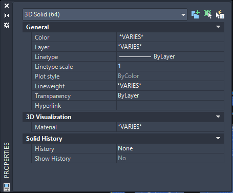
If we now select all objects we see they are all Solids. Of course that depends on the "Keep only Solids" option in the settings.