|
<< Click to Display Table of Contents >> Coordinates |
  
|
|
<< Click to Display Table of Contents >> Coordinates |
|
This chapter describes the various options of the Coordinates tab of the Settings dialog.
General
The "Coordinates" tab allows you to setup properties and default values for the coordinate function. Details can be found under Define Coordinate System.
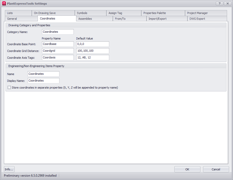
Drawing Category and Properties
The Coordinate function will work in Paper Space. So all settings here are related to this space and not Model Space.
Category Name:
The Name of the drawing category in Project Setup.
Coordinate Base Point:
Property Name for the Base Point and the Default Value. The Default Value can be typed in or you click on the icon to select a point in the drawing.
Coordinate Grid Distance:
Property Name for the Grid Distance and the Default Value. The Default Value can be typed in or you click on the icon to select the distanced in the drawing.
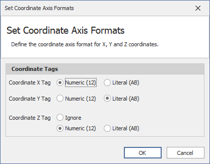
Coordinate Axis Tags:
Property Name for the Axis Tags and the Default Value. The Default Value can be typed in or you click on the icon to open the next dialog where you can define the format for each axis. And you can exclude the Z-Axis in case of 2D drawings like a P&ID.
Exclude Axis Tags:
Values which should not be used. For example: I or O. Every letter has to be separated by a ",". For example: I,O.
Engineering/Non-Engineering Items Propery
Name:
Name of the property for the Engineering and Non-Engineering Items classes.
Display Name:
Display Name of the property for the Engineering and Non-Engineering Items classes.
Store coordinates in separate properties
This stores X, Y, Z in separate properties and not just one.
Next Chapter: DWG Export