|
<< Click to Display Table of Contents >> User Interface |
  
|
|
<< Click to Display Table of Contents >> User Interface |
|
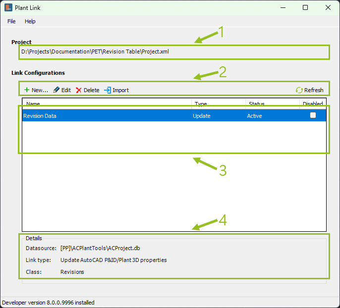
When opening the main dialog of PlantLink, you have the following sections:
1.This is shows the name of the current project.
2.Those are the various functions explained in the sub-chapters.
3.Those are the existing link configurations.
The column Name is the name you gave to the link configuration.
The column Type shows the type of the link configuration (Update, Extended, AutoCAD, Drawing).
The column Status should show Active and have a blue color. If there is some issue with a link configuration, then an error message is shown in the main form and the row is red.
The column Disabled allows you to deactivate a link configuration.
4.Some details about the selected link configuration.
Datasource shows where the data is coming from. This is either a SQLite database or a UDL file which then points to SQL-Server, MS Access, or MS Excel.
Link type is just a longer text for the type of link as shown in the Type column.
Class shows the class name for which the link configuration is setup.
All shown link configurations are listed in the project's \ACPlantTools\PlantLink\LinkConfigurations\LinkConfiguration.Collection.xml. If the file doesn't exist for an existing project it will be created automatically.
The LinkConfiguration.Collection.xml, LCF, UDL, MS Access, MS Excel files will also be added to the MISC database. This allows the files to be visible in Project Manager under the Related Files node, but also ensures, that the files will be copied when creating a project backup or use the project as a template for a new project.
Next Chapter: Creating a link configuration