|
<< Click to Display Table of Contents >> Create an AutoCAD Properties Link |
  
|
|
<< Click to Display Table of Contents >> Create an AutoCAD Properties Link |
|
This chapter describes how AutoCAD Property Links allow modifying AutoCAD properties like Layer, Color, LineType.
A link with the project created during this chapter is at the end of this chapter.
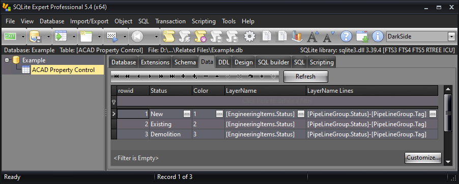
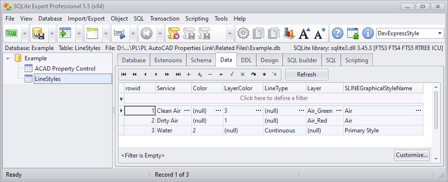
The table we use in this example has 4 columns. The column rowid is shown by default, but doesn't exist in the table. We want to update the AutoCAD Color and Layer of the P&ID Symbols and Pipe Line Segments. We will later see, that for Equipment Symbols we use the columns LayerName and for Pipe Line Segments we use LayeName Lines. As you can see in the two layer columns, you can also use Plant 3D classes and properties which will later be evaluated by PlantLink when needed.
|
![]() Setting up the Link Configuration
Setting up the Link Configuration
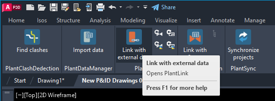
This time we will setup two link configurations. One for Equipment symbols and the other for Pipe Line Segments. To setup a link configuration we need to open the main user interface of PlantLink from the PlantTools ribbon.
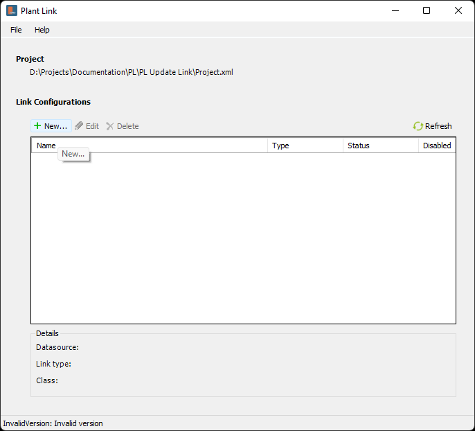
Next you click on New... to create a new Link Configuration.
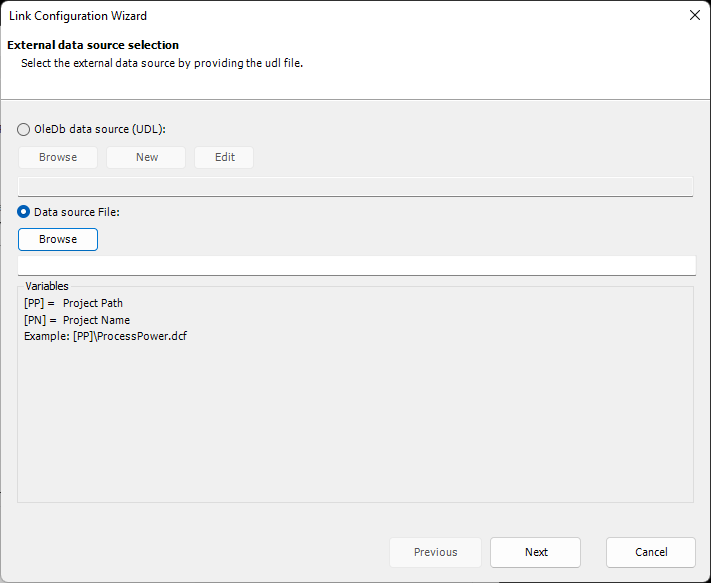
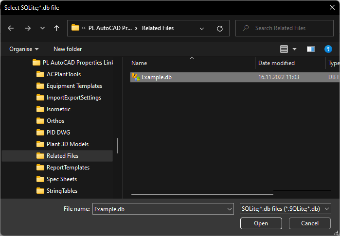
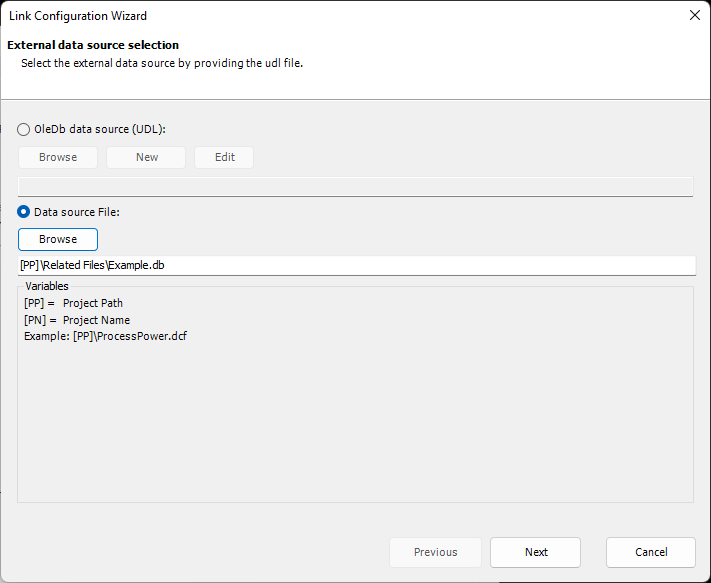
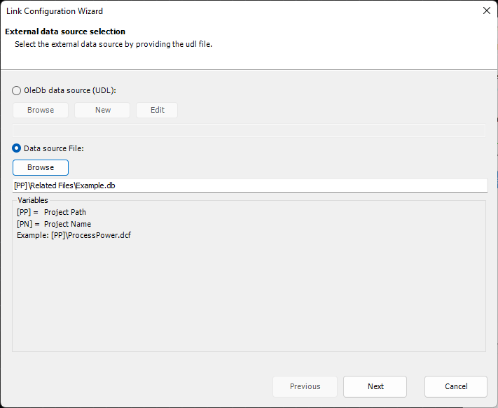
This opens the PlantLink Wizard. Since we are using an SQLite database you select Data Source File:. For all other data sources you have to use a UDL file. More about this under Use SQL-Server, Use MS Access, Use MS Excel. Click on Browse to open the file selector.
In this example, the SQLite database is stored in the Related Files folder in our project.
After you click Open the Wizard checks if the path to the database file can be change to a relative path. This makes it easier in case you later want to copy the project. Then there is no need to adapt the Link Configuration.
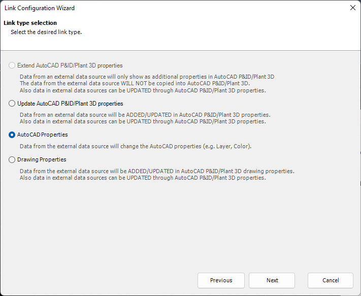
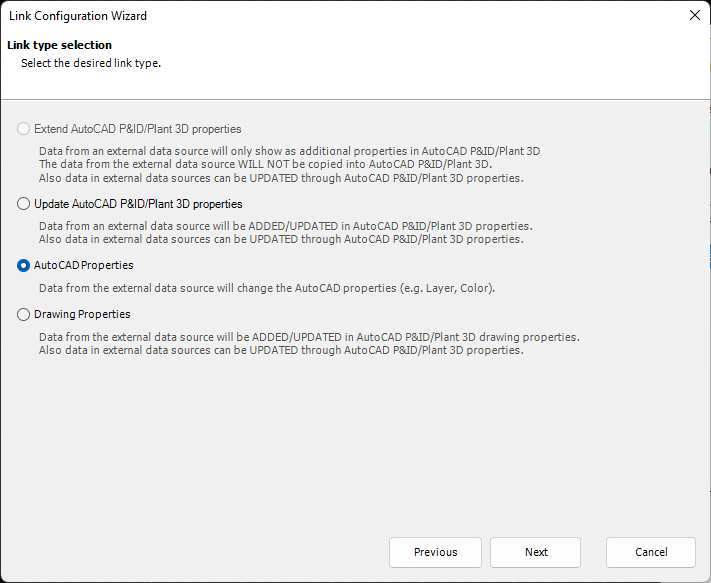
We keep the default selection Update AutoCAD P&ID/Plant 3D properties. The other options will be explained in the following chapters.
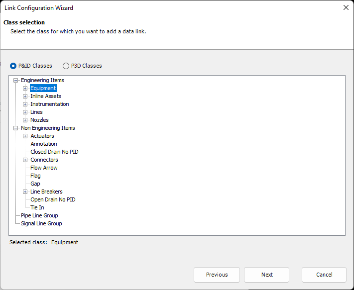
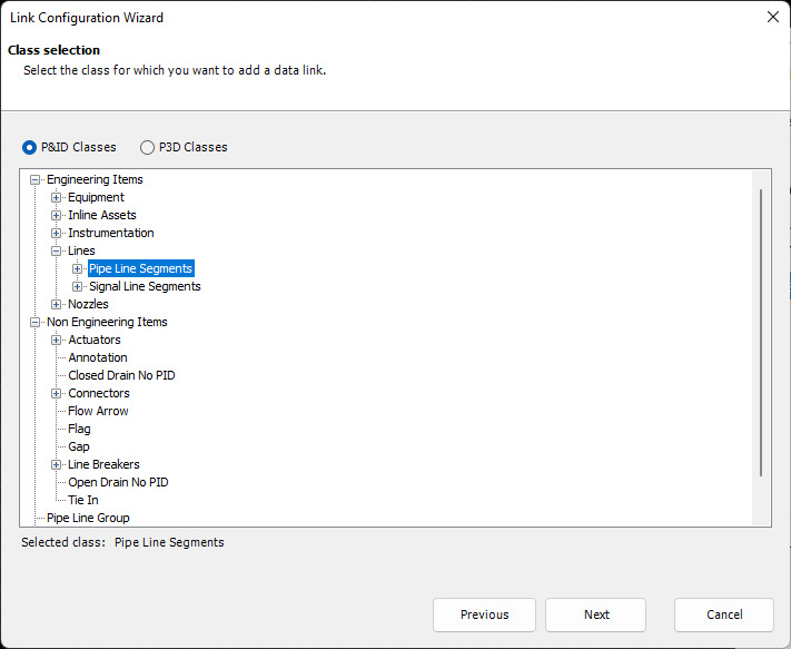
Since this table contains equipment catalog data, we select the Equipment class to map the data from the table to the equipment properties our P&ID symbols.
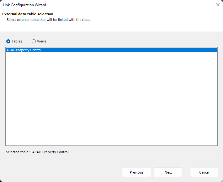
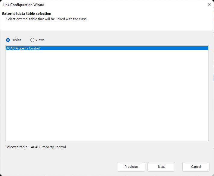
You can select Tables and Views from the database file. But in this case there is just one table available.
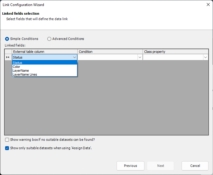
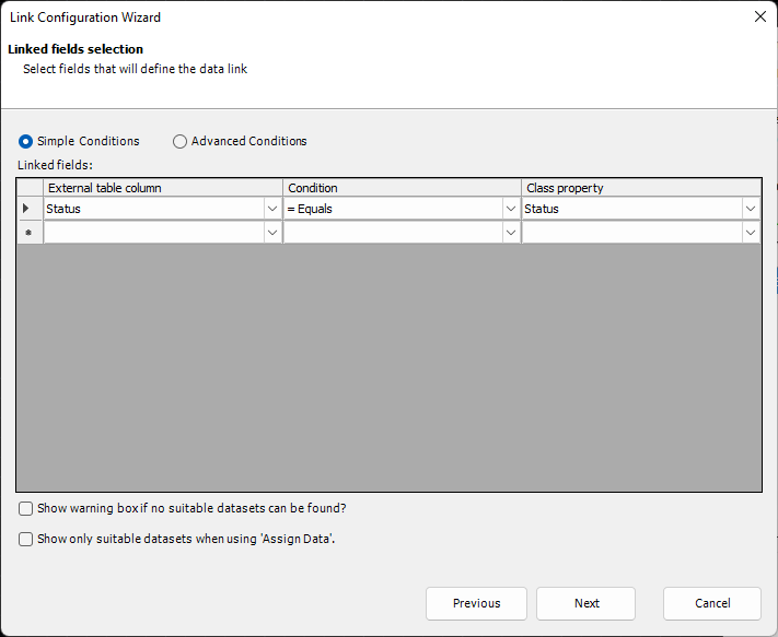
Now we need to define the linked fields. This essentially tells PlantLink how to find suitable rows/datasets in the table. It more or less filters the table. In this example, we use the Status from the table.
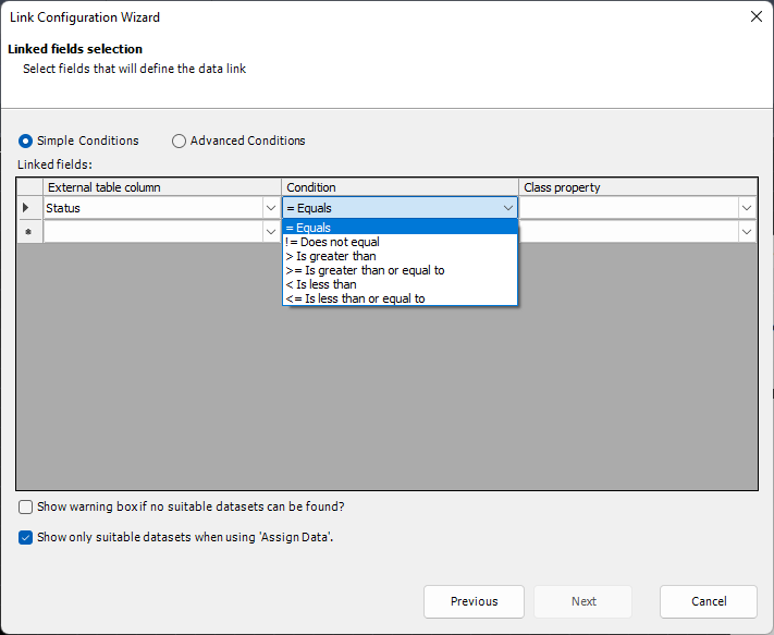
There are some standard Conditions available. We select = Equals, because the type of the equipment symbol is used to filter for Status in the table.
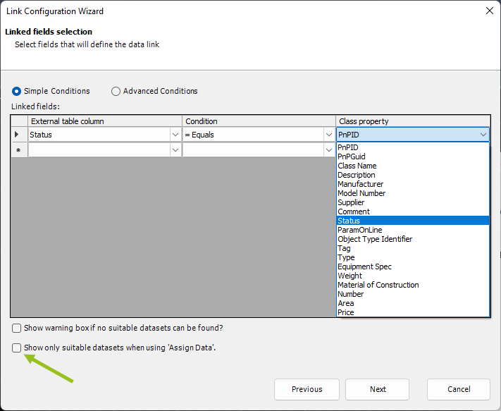
Select Type which contains the selection list with the various equipment types in our equipment symbols. The option Show warning box if no suitable datasets can be found opens a warning dialog informing you, that PlantLink couldn't find anything based on the linked column/property. Show only suitable datasets when using 'Assign Data' later limits the presented rows/datasets to only the ones where the linked columns/properties meet the set conditions. Otherwise the PlantLink - External Database Viewer will show all rows/datasets from the table. In this case we don't want to see the database viewer, because we are sure, that for each Status there is just one row in the table.
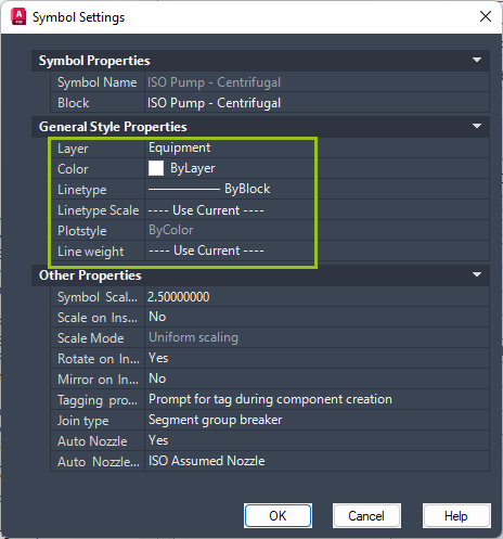
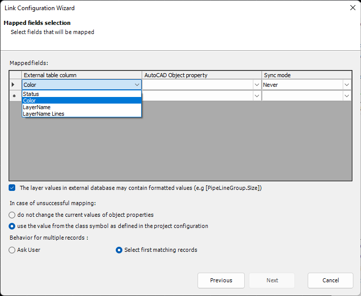
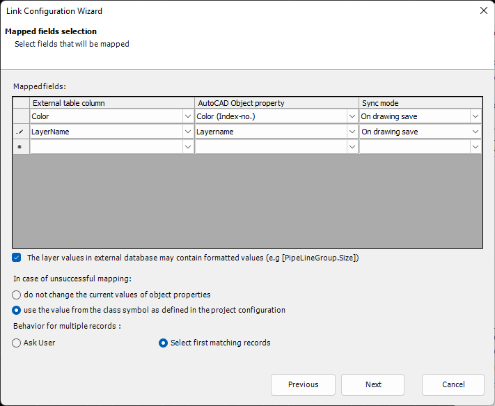
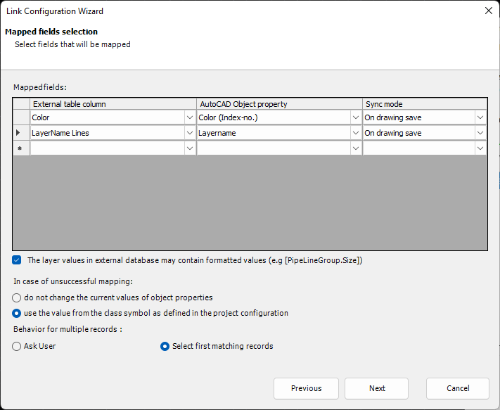
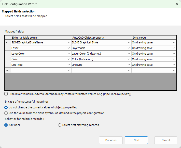
Next we define the columns from the table and map them to the AutoCAD properties. The order of the mapping defines the order of the columns when there are multiple choices. Although, this is unlikely for mapping AutoCAD properties, because typically there is just one choice. The option The layer values in the external database may contain formatted values needs to be check, because we use class and property names in the table which need to be evaluated. Meaning, that an expression like [EngineeringItems.Status] will result for example in New. The option for In case of unsuccessful mapping has to options. do not change the current values of object properties means, that the current AutoCAD properties of the symbol or line segment will stay as they are in case PlantLink cannot find a suitable row in the table. use the value from the class symbol as defined in the project configuration means, that in case PlantLink cannot find a suitable row the AutoCAD settings from project setup will be used.
The option Behaviour for multiple records controls what should happen, if there are more than one suitable rows/datasets. The default setting is Ask User. In this case the PlantLink - External Database Viewer dialog will show up and the user selects the correct row/dataset. When using Select first matching record PlantLink will just use the first of the found candidates from the table. Since we don't expect multiple choices in the table, we can set this option to Select first matching records.
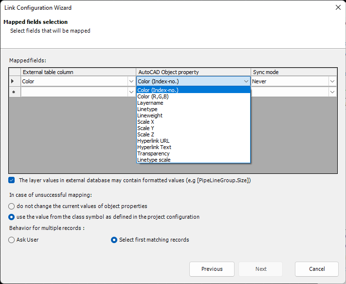
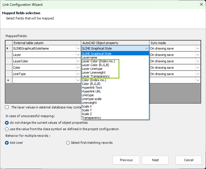
You select the column and the AutoCAD property to which the columns should be mapped. Let's start with Color (Index-no.). This AutoCAD property expects color numbers like 1, 2, 3 for red, yellow, green. There is also the option to use RGB in the table.
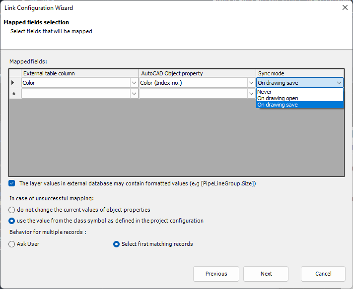
For Sync Mode we use On drawing save. This ensures, that the mapping for those properties will be refreshed when the drawing is saved, or closed and saved. So when you close and save your drawing, your mapped properties are up-to-date. More details about Sync Mode can be found under Mapping Options.
As the second mapping we choose the Layername.
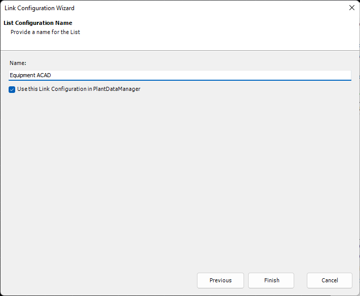
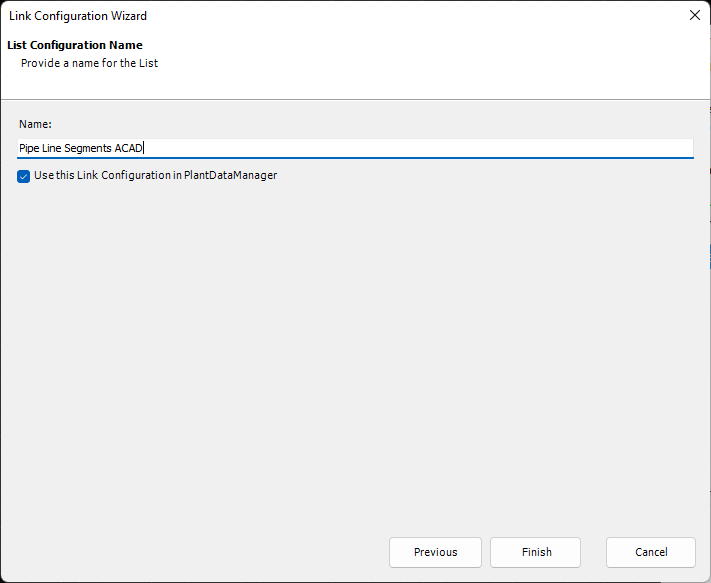
Lastly, we define the name of the Link Configuration. The option Use this Link Configuration in PlantDataManager tells PlantDataManager if this Link Configuration can also be used in PlantDataManager. Of course, in PlantDataManager we cannot change AutoCAD properties. Therefore, PlantDataManager will automatically ignore AutoCAD properties link configurations.
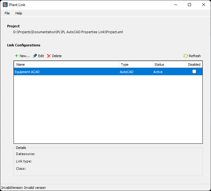
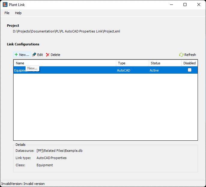
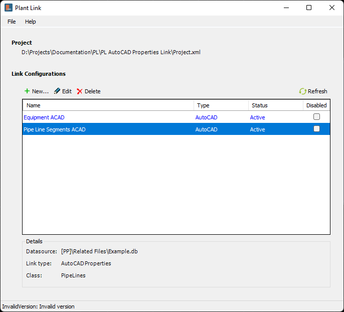
We now see the Link Configuration in the main dialog of PlantLink and it shows Active. The Link Configuration appearing in alphabetical order. This can become important when Link Configurations depend on each other and must be executed in a certain order (see Rename, Edit, Delete, Deactivate Link Configurations).
For the Pipe Line Segments we need a second link configuration. We start again with New...
We select the same database file as before.
Again AutoCAD Properties.
This time we select the Pipe Line Segment class.
We select the same table.
We link the same column and property.
For the Layername we now select LayerName Lines.
And finally a name.
And now we have two link configurations.
|
![]() Testing the Link Configuration
Testing the Link Configuration
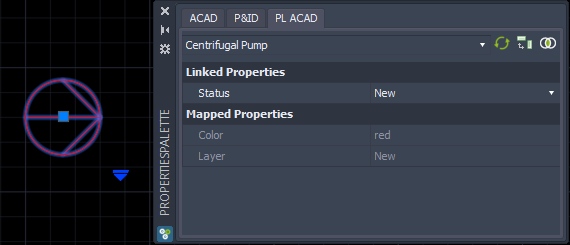
When we insert a pump symbols it uses the AutoCAD properties setting from project setup while being inserted.
When the Assign Tag dialog is closed we see that the symbol is red and the Layer is the same as the Status.
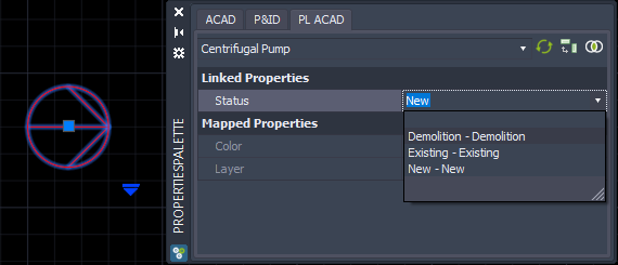
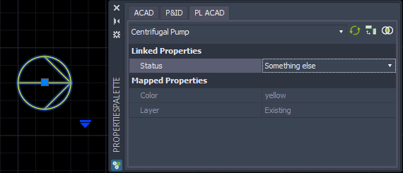
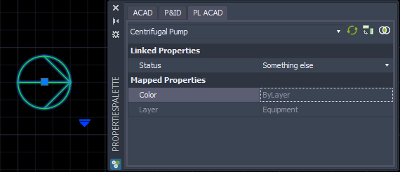
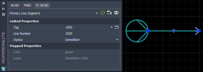
When changing the Status in the Property Palette...
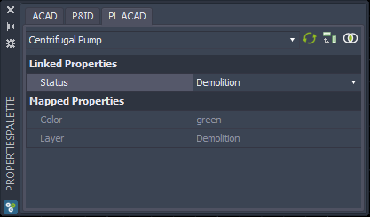
...the Color and Layer will change accordingly. Be aware, that the properties change only when your mouse leaves the PropertiesPalette.
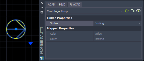
And again with a different Status.
If you type in something which is not in the table...
...then the color and layer defined for this symbol in project setup will be used.
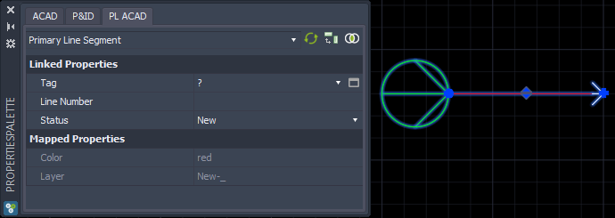
If we draw a Pipe Line Segment, then we see the Status used as the first part of the Layer.
After saving the drawing the Color will be updated too, because the saving updates the link configurations.
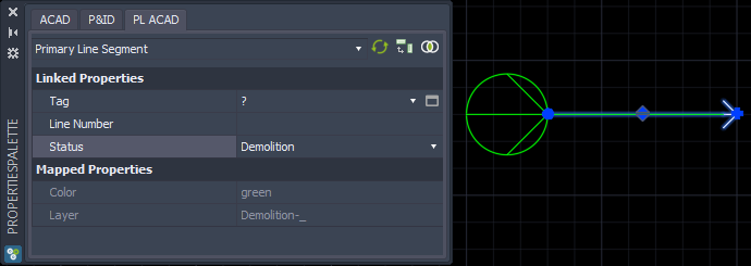
If you change the Status the Color and layer will be updated again.
When editing a Line Number for the Pipe Line Group, the Layer will be updated too.
|
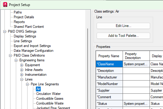
AutoCAD Multi-Lines or MLINEs work differently than regular Line Types (POLYLINEs). Not just in Plant 3D, but also in standard AutoCAD itself. This section only explains the specialties when you want to use MLINEs. Make sure you read and understand the sections above from this chapter. We concentrate only on handling the Line Styles for MLINEs and POLYLINEs and the coloring. The other AutoCAD settings like LineTypeScale or LineWeight are no different with MLINEs. To use MLINEs in the first place you have to create Pipe Line Segment styles in Project Setup.
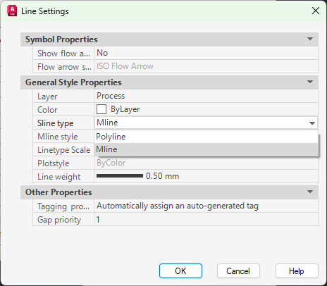
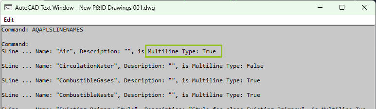
Make sure the Sline type is set to Mline
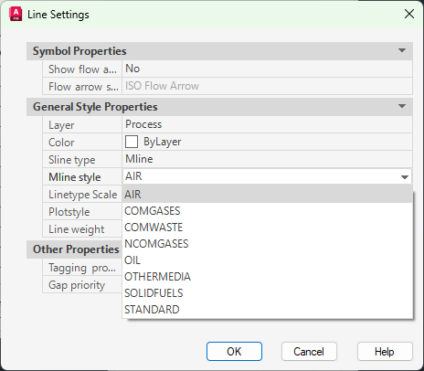
And that you selected a MLINE Style. The MLINE Styles will be read from the projSymbolStyle.dwg in your project. That means, you have to make sure, the the MLINE Styles are loaded into this drawing before you can select them in the dialog.
For this example we have the following table.
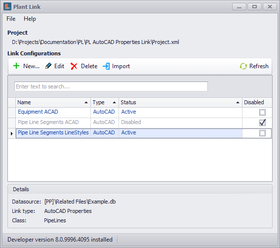
The sample project at the bottom contains a separate line configuration for MLINEs. For testing make sure, that you deactivate the Pipe Line Segments ACAD link and activate the Pipe Line Segments LineStyles link.
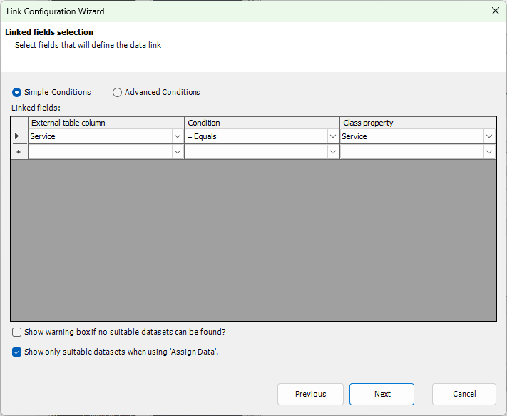
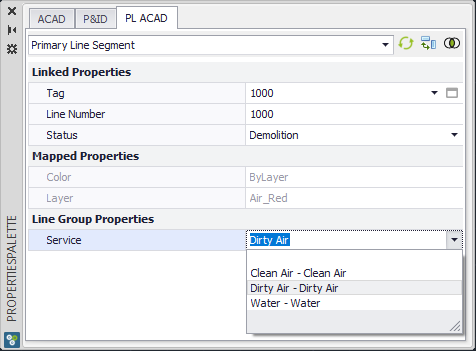
If you edit the link you will see, that the Service property is linked to the Service column in the table. Remark: The Service property of the Pipe Line Group is acquired by the Pipe Line Segment class.
In the first row you see that SLINE Graphical Style is selected for the AutoCAD Object property. This property must the first one in the list. If you do not add it at the top row, then the Wizard will do this for you when the Wizard is closed at the end.
We controlling the Layer settings for the MLINEs we added more properties.
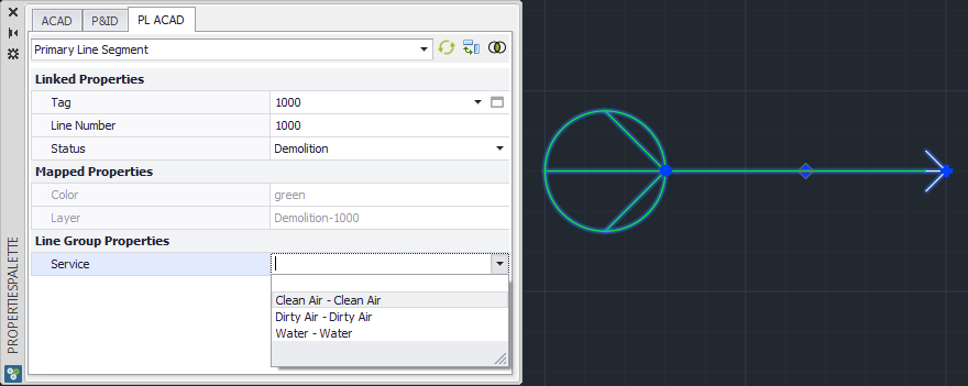
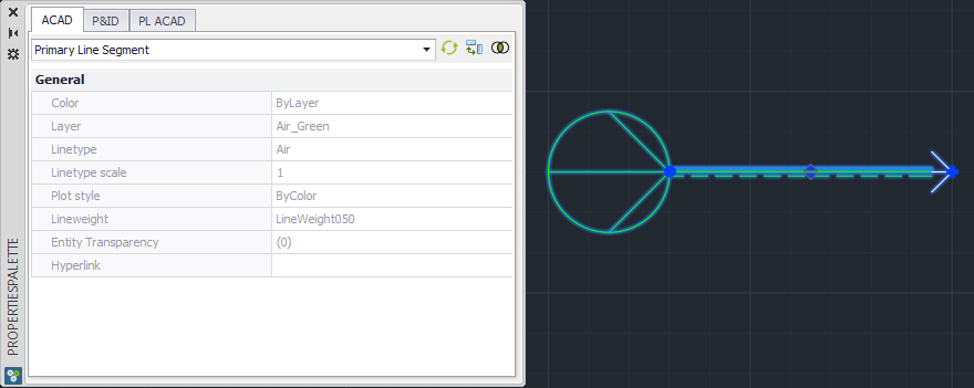
The settings of the Layer properties can also be used for other cases than just MLINEs. Now we start selecting Clean Air as the service.
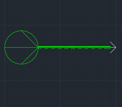
As soon as we move the mouse outside of the Properties Palette (or when closing the Assign Tag dialog to edit the Service) the Line Segment will be updated.
When we look at the AutoCAD properties we will see, that the Line Segment is on Layer Air_Green.
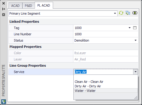
Next we change it to Dirty Air.
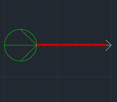
Now the line is red.
Looking at the Layer we see, that the layer was updated.
Now we select Water.
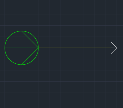
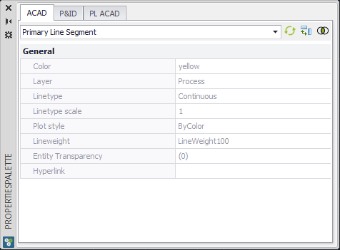
We get a simple continuous line in yellow.
If we look at the AutoCAD properties we see the color was set by PlantLink to yellow. Since there was no layer given in the table for this service, PlantLink will use the layer from Project Setup for this Pipe Line Segment class.
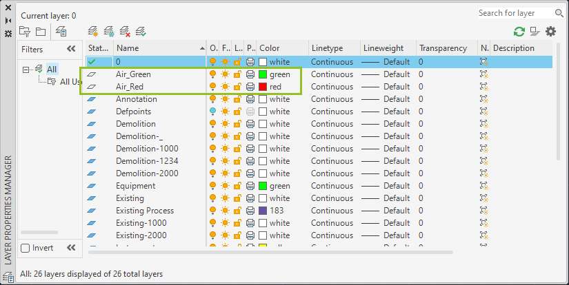
If you look into the Layer Manager you will see, that PlantLink created the Layers and set the color.
|
Next Chapter: Create Drawing Properties Link