|
<< Click to Display Table of Contents >> Inserting Reducers on Nozzles directly (3D) |
  
|
|
<< Click to Display Table of Contents >> Inserting Reducers on Nozzles directly (3D) |
  
|
This chapter describes how to insert reducers on an equipment nozzle directly.
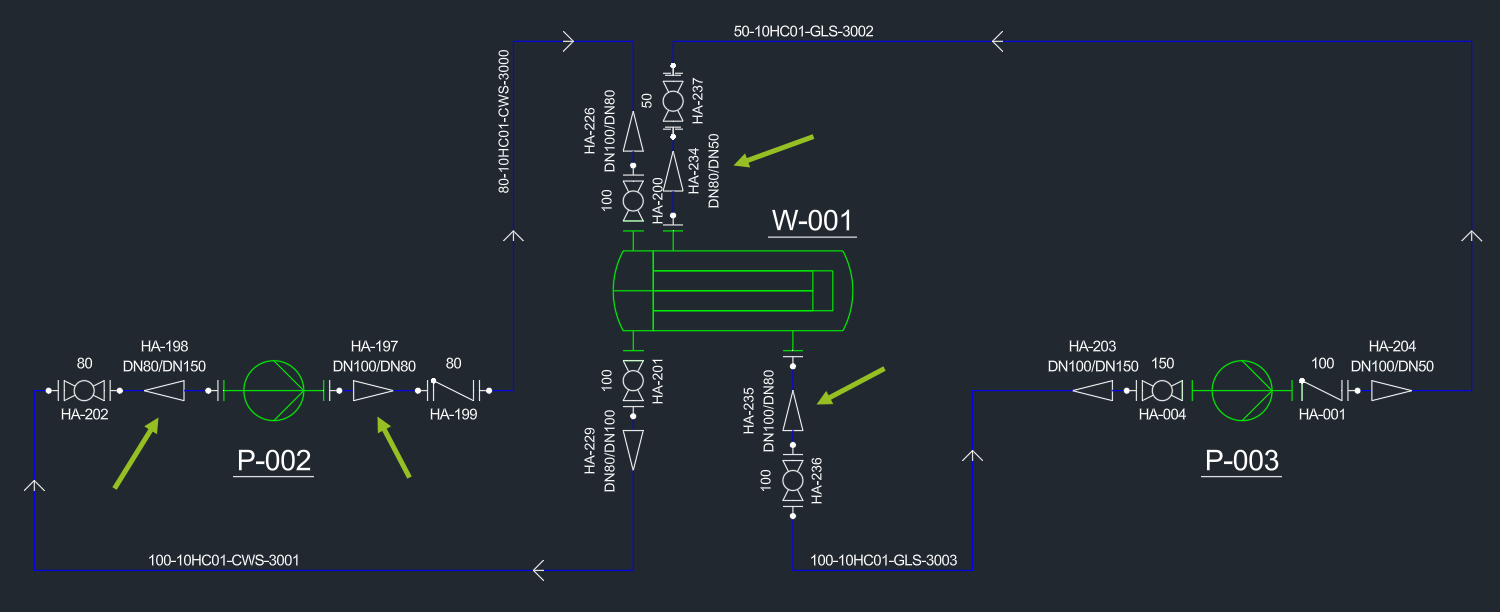
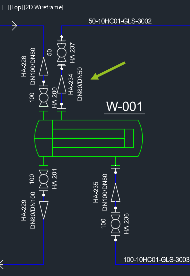
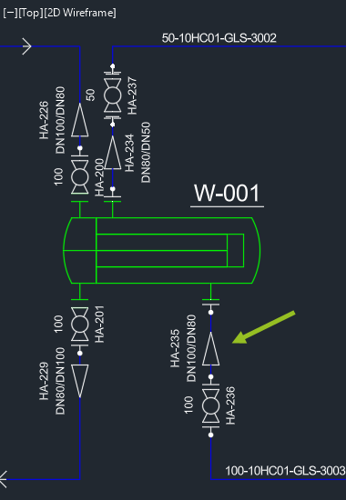
We use this example where the 4 marked reducers will be inserted in 3D directly on the equipment nozzles.
The image also shows the Tags of the reducers which were added to make it easier to follow the steps.
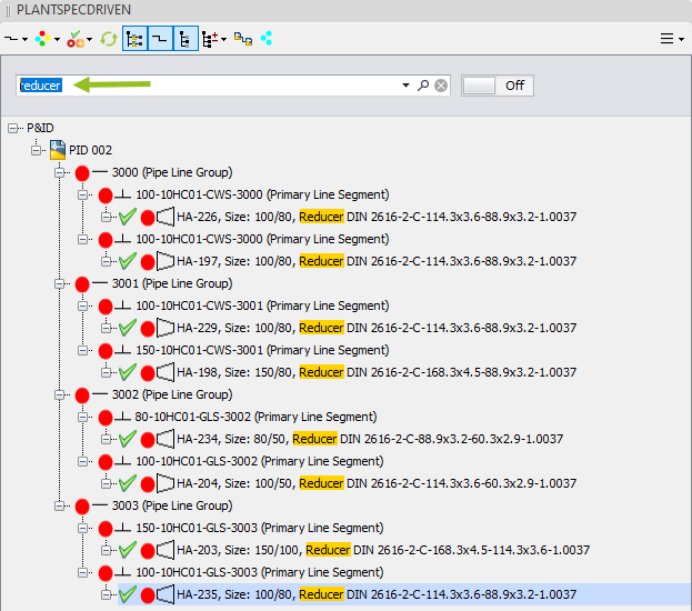
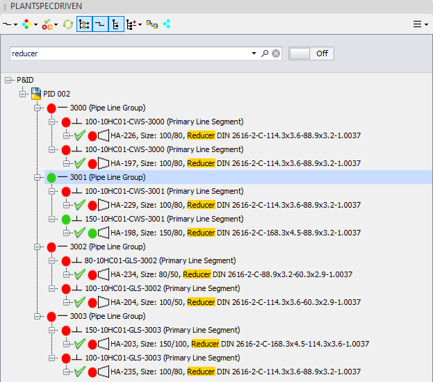
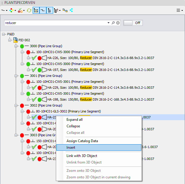
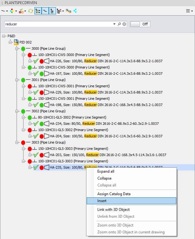
For the purpose of this chapter we can also filter the tree for the word reducer to make it easier to find the reducers.
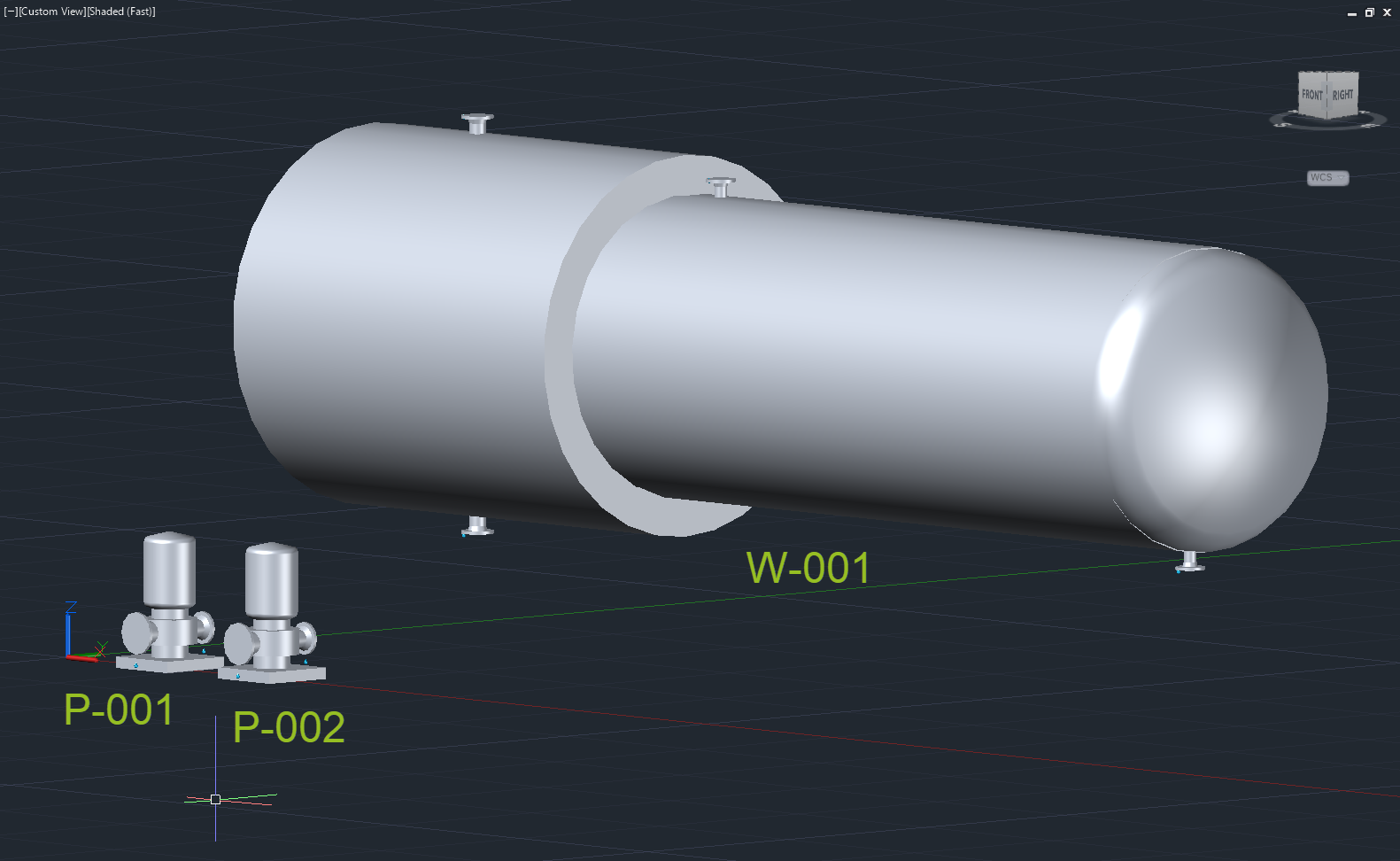
The 3D drawing looks like this.
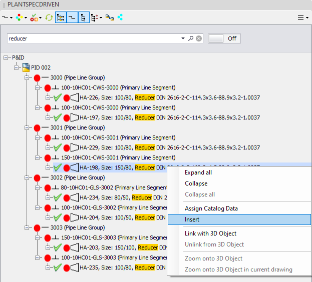
Let's insert the reducer HA-198 which will be inserted on the suction side of P-002.
If the reducer is on your mouse you have to make sure if you need the smaller or larger side on your mouse.
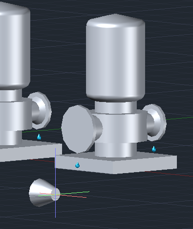
If you look at the PID you will see, that you need to insert the reducer with the larger side on the nozzle.
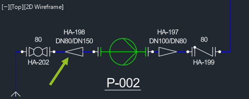
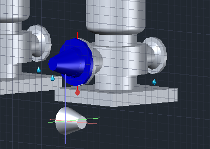
Therefore you press the CTRL key once to flip the reducer.
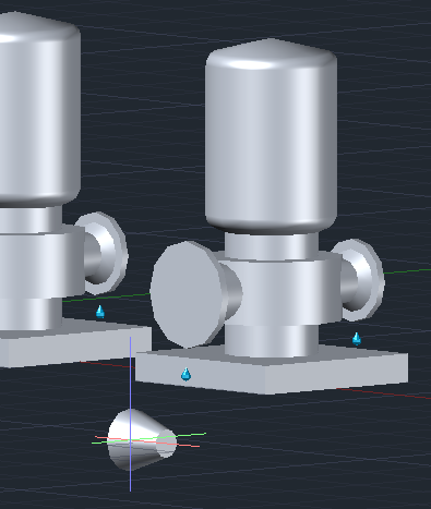
Now you insert the reducer on the nozzle. Plant 3D will automatically created a joint with a flange and connector (gasket + boltset). After this you rotate the reducer if needed.
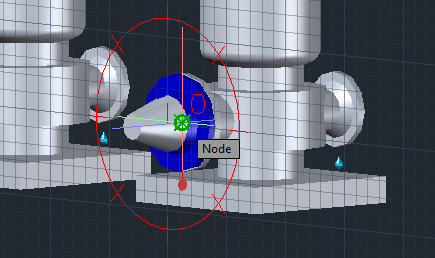
Finally, press the ESC key to stop the continuous insertion.
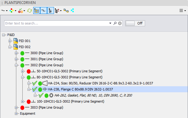
In the structure tree you now see, that the reducer, the line segment and the line group are all linked.
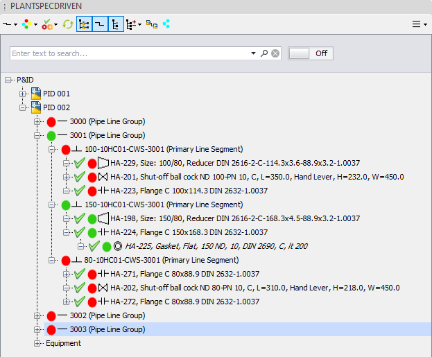
If you remove the filter of the structure tree you can also see, that the flange and gasket are linked.
Typically, we link pipes and elbows to the P&ID Line Segment (see Linking P&ID Line Segment (3D)). However, there is no pipe or elbow between the reducer and the nozzle. Therefore, PlantSpecDriven will link the connector between the reducer and the flange as the proxy to the P&ID Line Segment.
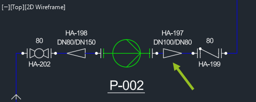
Let's insert the reducer of the discharge side of P-002.
Filter the tree again if needed and use Insert.
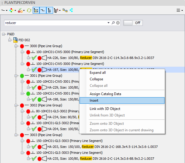
This time we don't need to flip the reducer, because you need the reducer on the larger diameter.
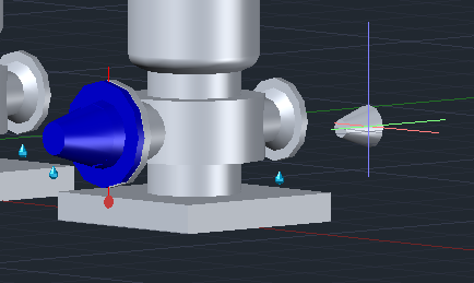
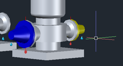
You insert the reducer, rotate it and press ESC to stop the continuous insertion.
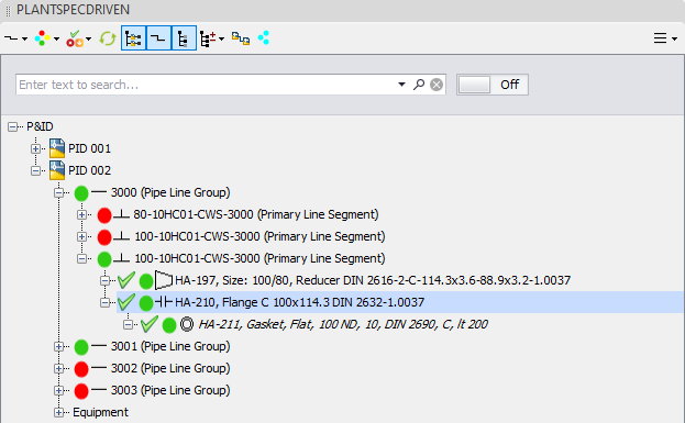
In the structure tree we see, that everything is linked.
Next we will insert the reducer at the top of the heat exchanger.
Filter the structure tree again if needed.
According to the P&ID drawing we need to insert the reducer with the larger side.
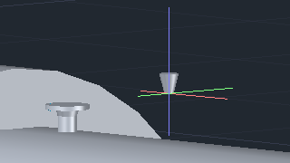
Therefore, press CTRL once.
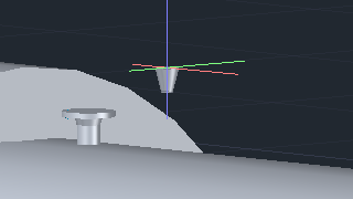
The insert, rotate, press ESC again.
And everything will be linked again.
Finally, the reducer at the bottom of the heat exchanger.
We filter again and insert.
This time according to the P&ID drawing, we need to insert the reducer with the smaller diameter on the nozzle. Meaning no CTRL is needed.
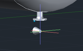
And we insert, rotate and press ESC again.
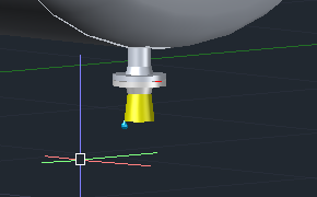
But now there is a difference compared to the other cases we had above.
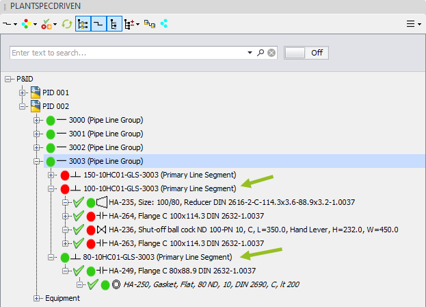
The reducer was linked, but not the line segment the reducer is under. This is because the line segment with size 100 will start from the reducer and continue from there. Meaning, if you start routine this size 100 line segment later the line segment will then be linked to the pipes and elbows of the routine you will create.
However, the line segment of the linked flange and gasket is linked. And as described earlier, since there is no pipe or elbow between reducer and nozzle, the link will be created between the connector between the reducer and the flange, and the P&ID line segment.
Next Chapter: Inserting Valves on Nozzles directly (3D)