|
<< Click to Display Table of Contents >> Inserting Valves on Nozzles directly (3D) |
  
|
|
<< Click to Display Table of Contents >> Inserting Valves on Nozzles directly (3D) |
|
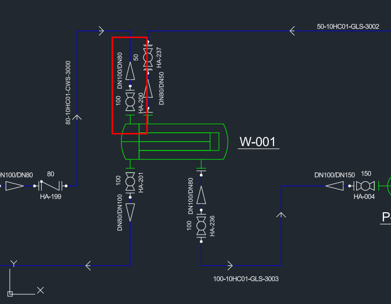
This chapter describes how to insert valves on an equipment nozzle directly.
This chapter is similar to the previous one where Reducers were inserted directly onto equipment nozzles.
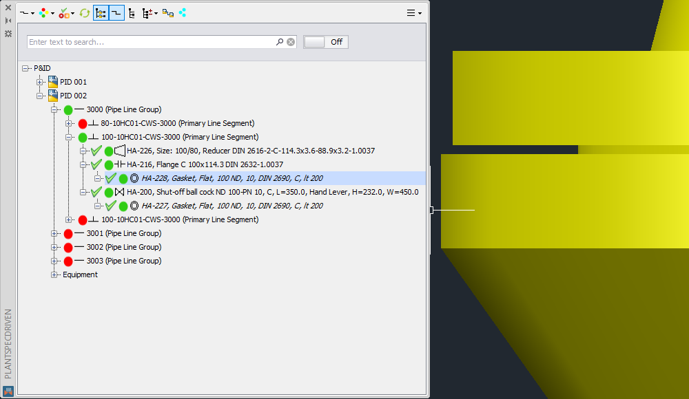
This time we will concentrate only on this nozzle with valve HA-200 and the following Reducer. However, we will see two variations.
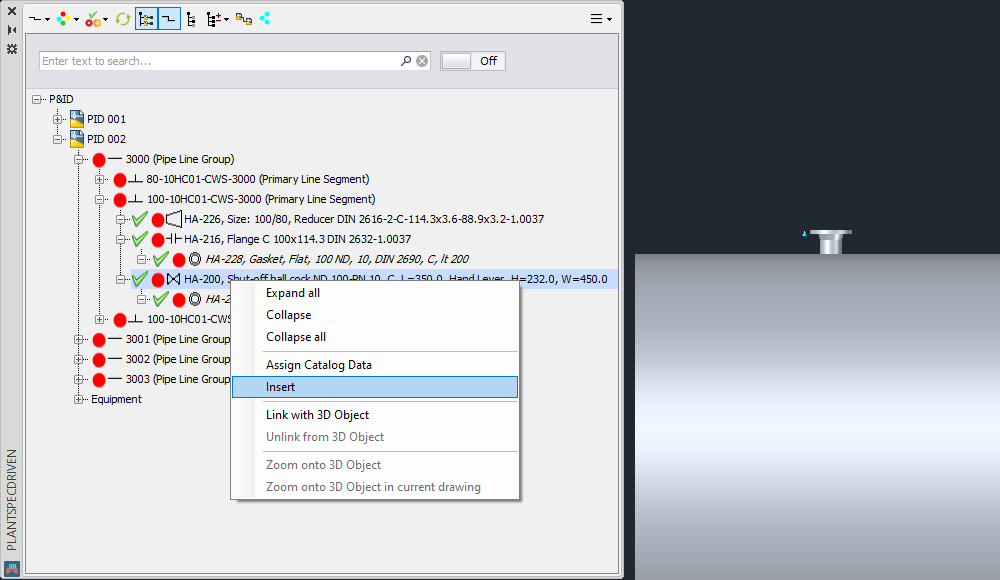
Variation 1: Here we will first insert the Valve and then directly on the Valve we insert the Reducer
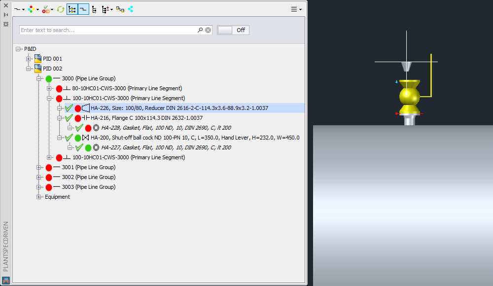
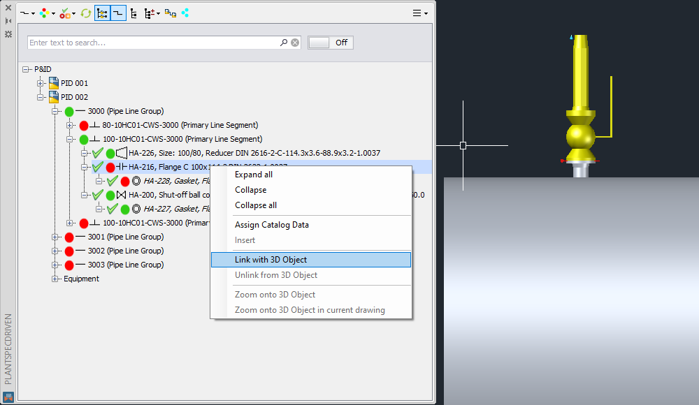
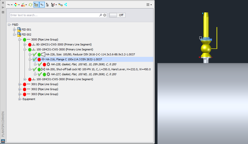
We insert the Valve.
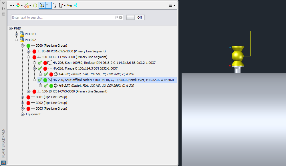
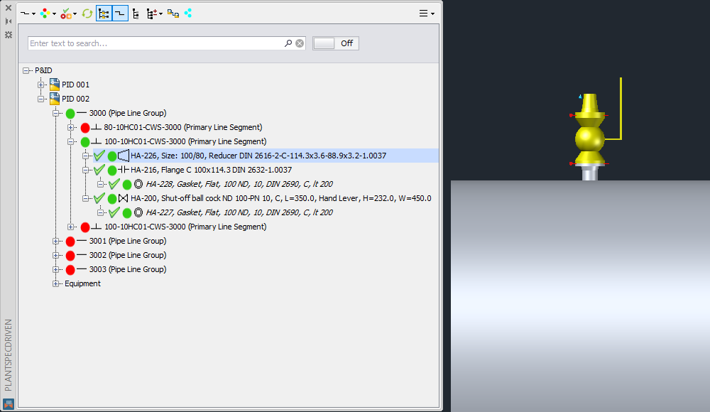
Through Plant 3D the Gasket will be inserted automatically. Valve and Gasket will be linked to the P&ID Valve and Gasket.
The Pipe Line Group will also be linked. You may have to refresh the tree to see the green status icon on the Pipe Line Group.
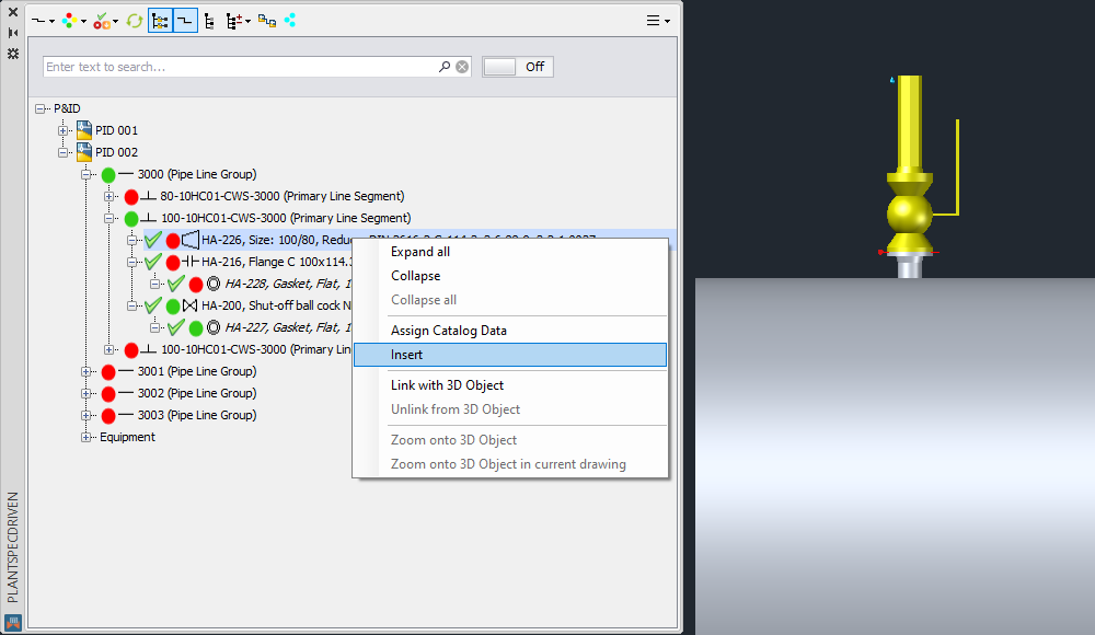
Next the Reducer.
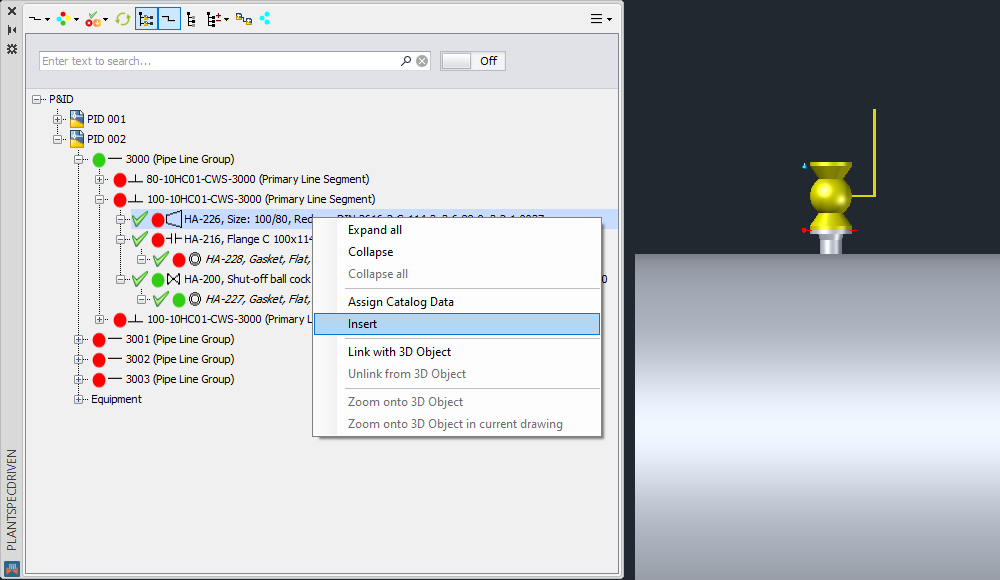
As in the chapter before, make sure you check whether you need to flip the Reducer with the CTRL key or not. In this case we want to insert the Reducer with the larger size on the Valve and therefore flip the Reducer.

Now the Reducer is hanging with its larger side on the mouse.
After finishing the insert the automatically inserted Flange and Gasket will be linked as well as the Reducer.
To show, that the P&ID Pipe Line Segment is linked as well the Connector (Weld) between the Reducer and the Flange will be used.
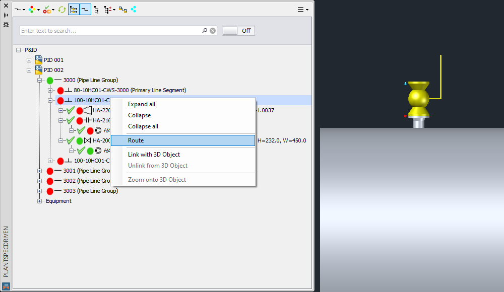
Variation 2: Here we will first insert the Valve and then a piece of pipe before inserting the Reducer
Inserting the Valves is the same as in Variation 1. We now continue with a bit of pipe or routing in general.
The pipe will of course be linked to the P&ID Pipe Line Segment.
Now we continue with the Reducer. Again make sure you check whether the Reducer must be flipped or nor.
In this case the Flange and Gasket will NOT automatically be linked. We need to manually link them.
Let's start with the Flange.
We select the 3D Flange at some point.
Now the Gasket.
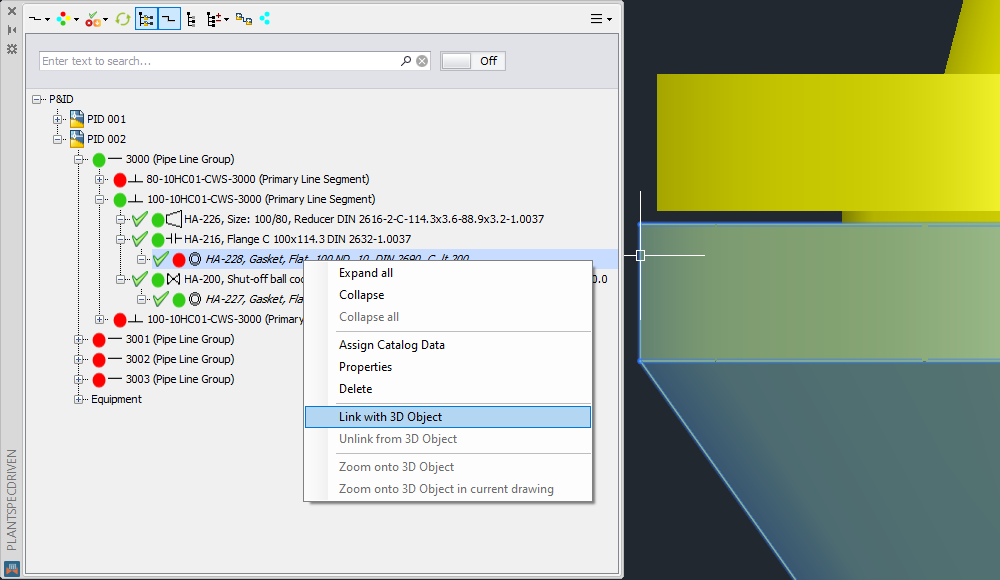
You now use the CTRL key and select the 3D Gasket.
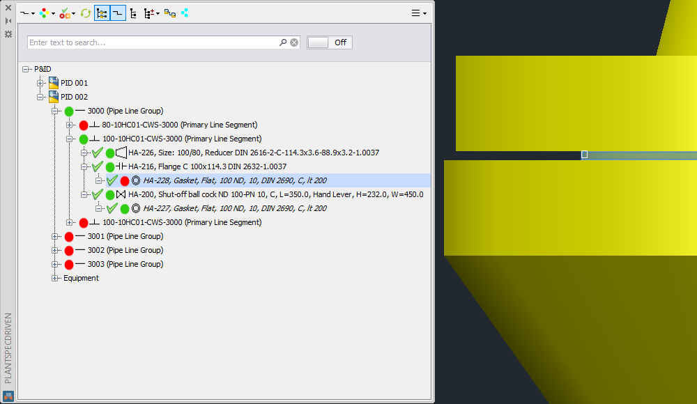
Now the Gasket is linked as well.
Next Chapter: Linking P&ID Symbols and 3D Object (P&ID/3D)