|
<< Click to Display Table of Contents >> Stacked Assemblies with Mapping |
  
|
|
<< Click to Display Table of Contents >> Stacked Assemblies with Mapping |
|
This chapter explains how you can use the mapping option for Assemblies instead of using Acquisition Rules.
You can also checkout the video which shows the setup and usage of this use case. This video also shows how the result looks in PlantReporter.
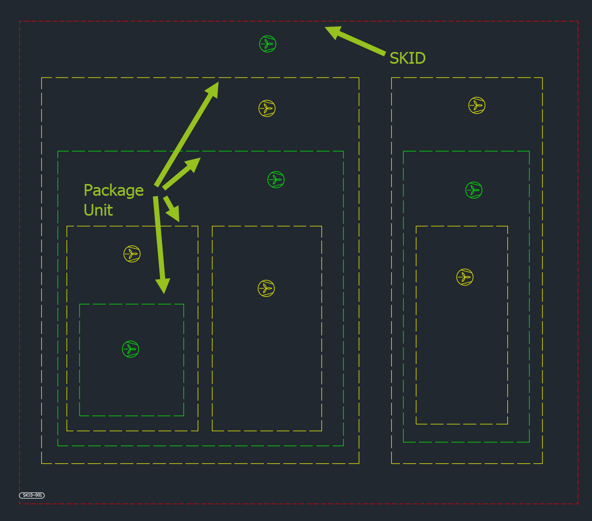
We will use two types of Assemblies. The outer most one is a SKID Assembly. And all other ones are Package Units with in the SKID.
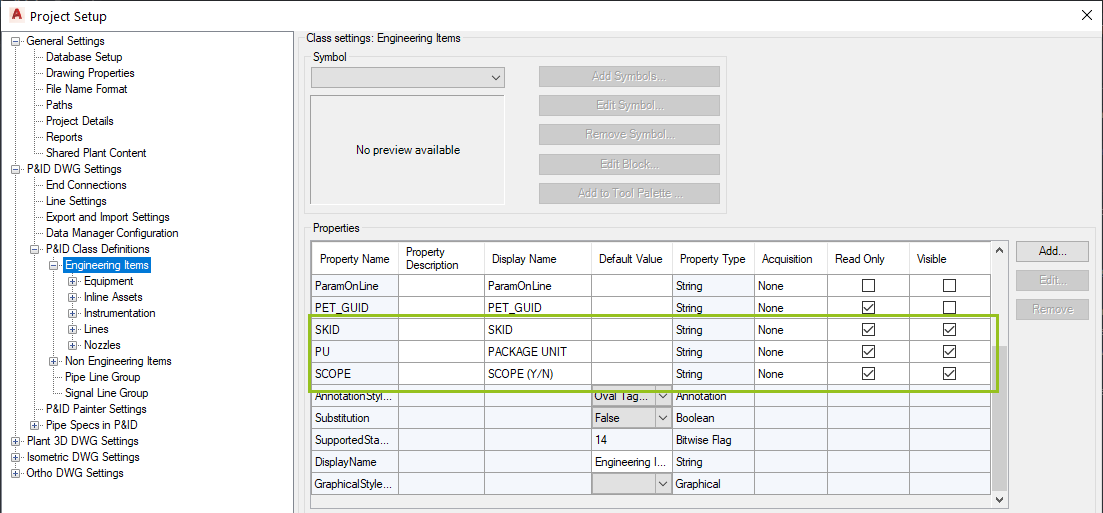
Creating properties
The first thing we do is create some properties under Engineering Items. These properties will later get the values from the Assembly properties. It is recommended, that these properties are defined as read-only. Otherwise the user may override them and the Assembly function will just remap the values and therefore delete the values.
Setup Assemblies in PlantExpressTools Settings
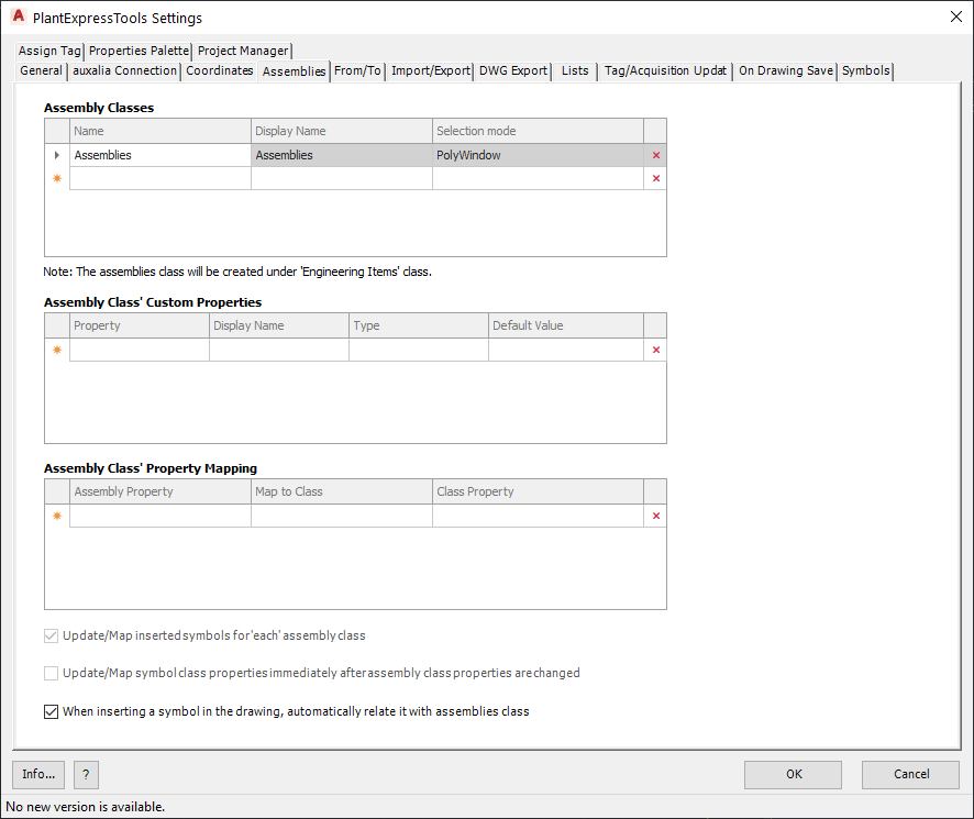
Now we can setup the Assemblies in the PlantExpressTools Settings dialog.
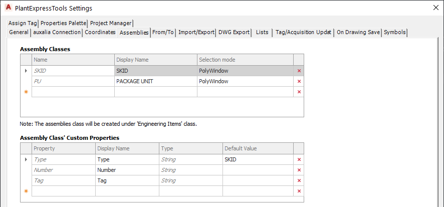
Click on the "Assemblies" tab to see the new options for mapping properties with Assemblies.
As always, there is the default class with the name "Assemblies".
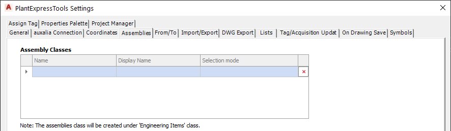
Since we don't need the Assemblies class we can either rename the class or delete it.
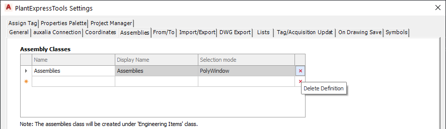
After you clicked on delete, the class is gone, but also would be the properties you may have created.
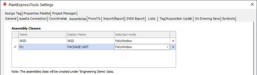
We create two different Assembly classes. As always you can choose between PolyWindow and PolyCross.
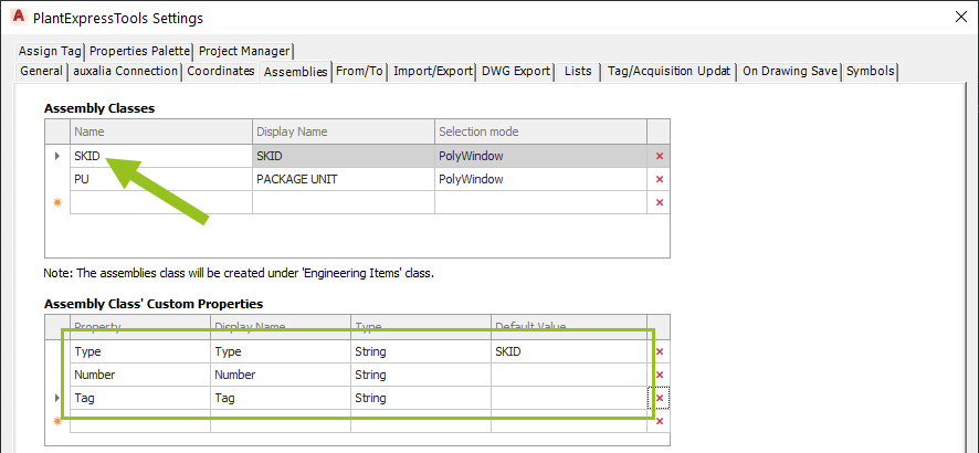
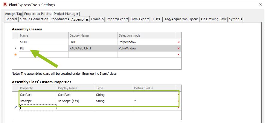
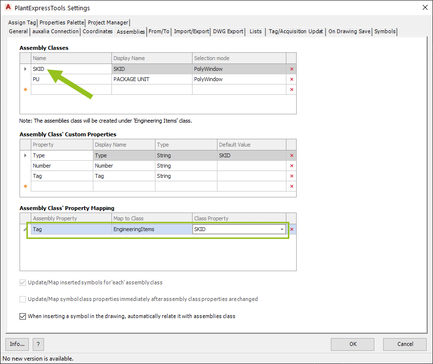
Next we click on the first class and create the three properties. For the "Type" you have the choice between String, Numeric, and Boolean.
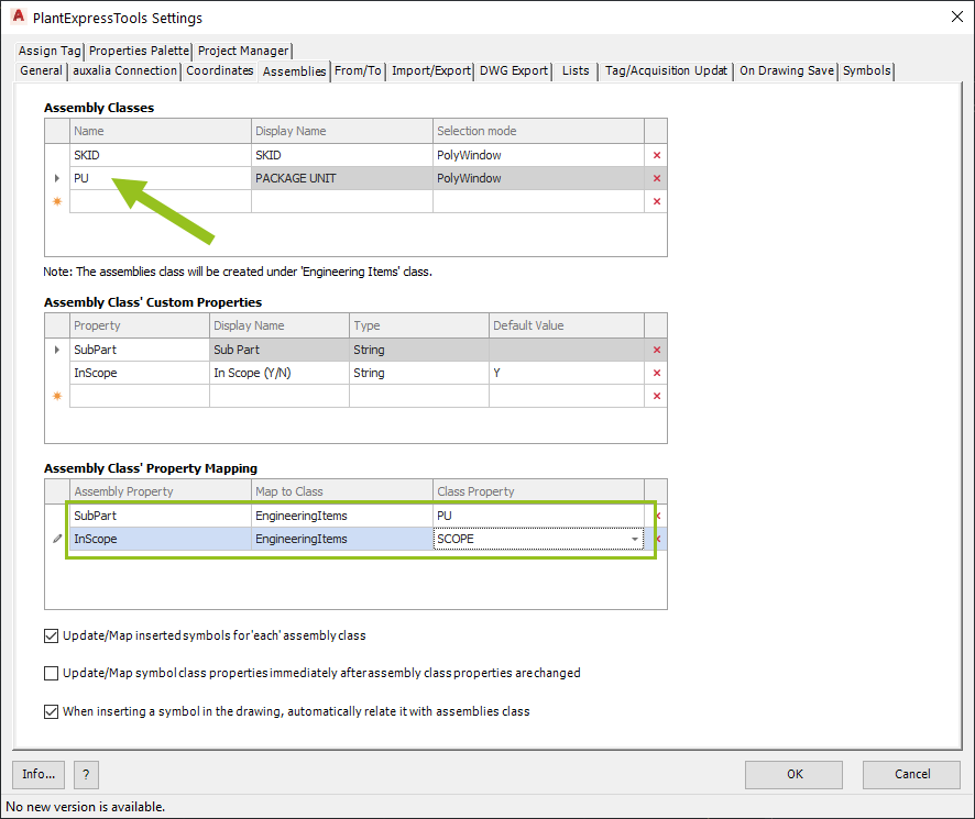
For the second Assembly class we need two more properties.
Lastly we use the new mapping of the Assembly class' properties to the properties of the symbols and line segments.
In the first column you select the property of the class. In the second column you select the class where the receiving property is located. Typically it is the EngineeringItems class. This is why we preset the column with the EngineeringItems class. In the third columns you then select the property of the selected class which will get the values from the Assembly class' property.
For the second Assembly we need two more mappings.
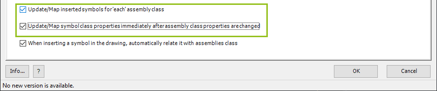
There are two more checkboxes which are specific to the mapped properties.
The first one is checked by default. It ensures, that the mapping is done for each of the defined Assembly classes for which a mapping is defined. If a symbol/line segment is surrounded by the same Assembly class multiple times (as in the example above), the mapping is done for the closest surrounding Assembly.
The second checkbox ensures, that the mapping is done, right when inserting the symbol/line segment.
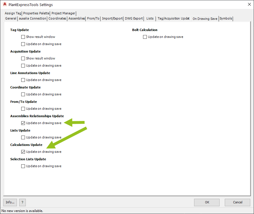
It is recommended to use the checkbox for the Assemblies on the "On Drawing Save" tab. This ensures, that the mapping is done or updated when the drawing is saved.
Since is this example the Assemblies and symbols/line segments are colored by the Calculation function (Calculate AutoCAD Properties) you may also want to consider checking the box for the Calculations
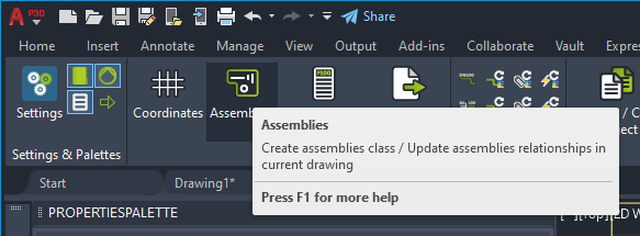
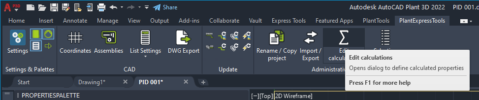
After closing the the Setting dialog, you click on the Assemblies button.
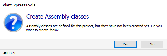
As always a dialog shows up where you can still can terminate the creation of the classes and properties.
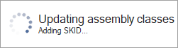
A progress panel appears where you can see which classes and properties are being created.
If you look again at the Settings you will see that the classes and properties are in italic font indicating, that the classes and properties were created. You cannot make any changes to the class/property names and data types anymore after the classes/properties were created. You would need to delete them and created them with the new name.
Creating Calculations for coloring
This section is not required for mapping, but it help to better see what's happening when later inserting a symbol or line segment.
We use two calculations. One for coloring the Package Unit Assemblies and one for coloring the symbols.
We click on the calculation function to open the dialog.
We click on "New...".
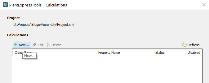
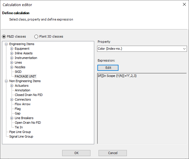
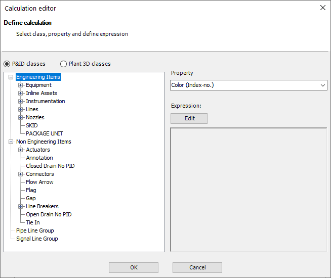
We select the "PACKAGE UNIT" class and select the "Color (Index-no.)" in the Property dropwown. Then click on "Edit".
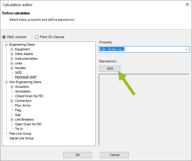
The Expression Editor opens where we use the following expression. What it does is, that it checks if the InScope property contains a 'Y'. And if so, the color will be set to 2 (Yellow). Otherwise the color will be 3 (Green).
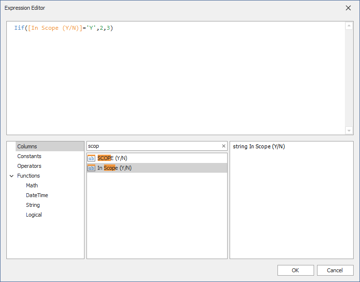
This isn't foul-proof, because the allowed values are Y and N. So, we could also check for 'N' if it isn't 'Y'. And if it isn't 'N' either we could use a different color.
After closing the Expression Editor the expression shows up in the "Calculation editor" dialog.
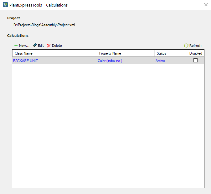
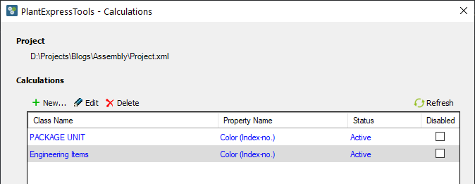
After another click we see that the calculation is blue and Active which shows that everything is ok.
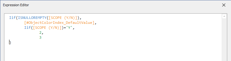
The second calculation is for the Engineering Items class which is essentially everything.
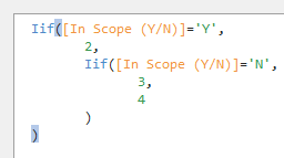
This is how the expression looks like.
First it checks if the SCOPE property is empty. This is for the two Assembly classes where this property will be empty. If it is not empty, the it is either 2 or again as before.
Again it is blue and Active.
Finishing settings in Project Setup
Now we need to make some final changes to the Project Setup.
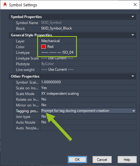
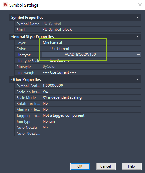
We start with the SKID class and click on "Edit Symbol...".
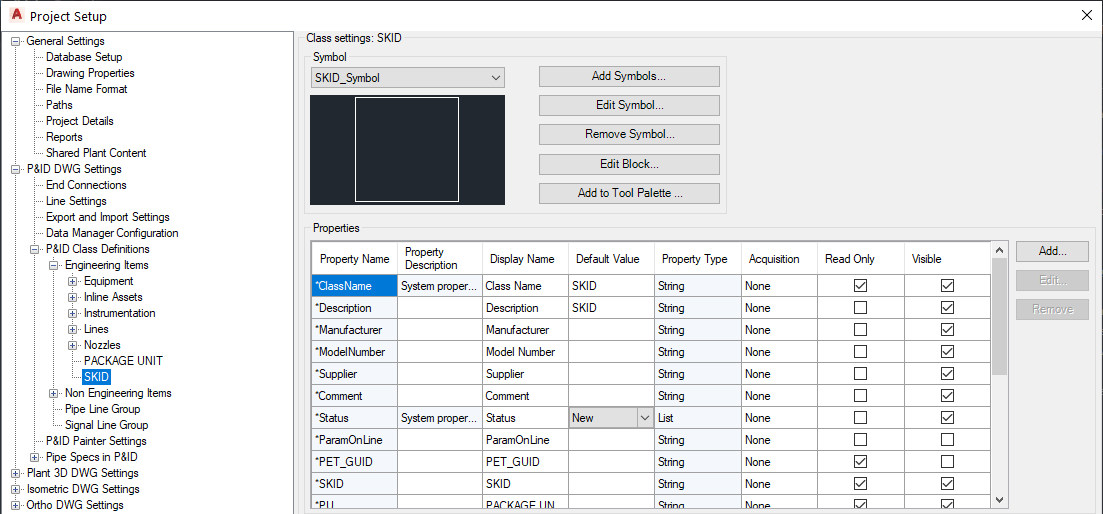
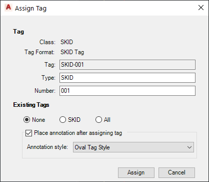
Here we set the Layer, Color and Linetype. And since the SKID Assembly has a Tag we must set the Tagging prompt to either Automatic or Prompt.
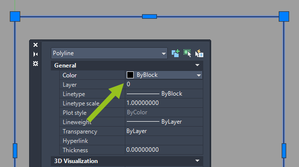
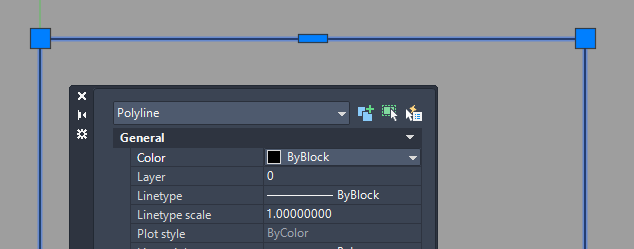
We also have to set the color for the block to "ByBlock" in order to have the calculation working.
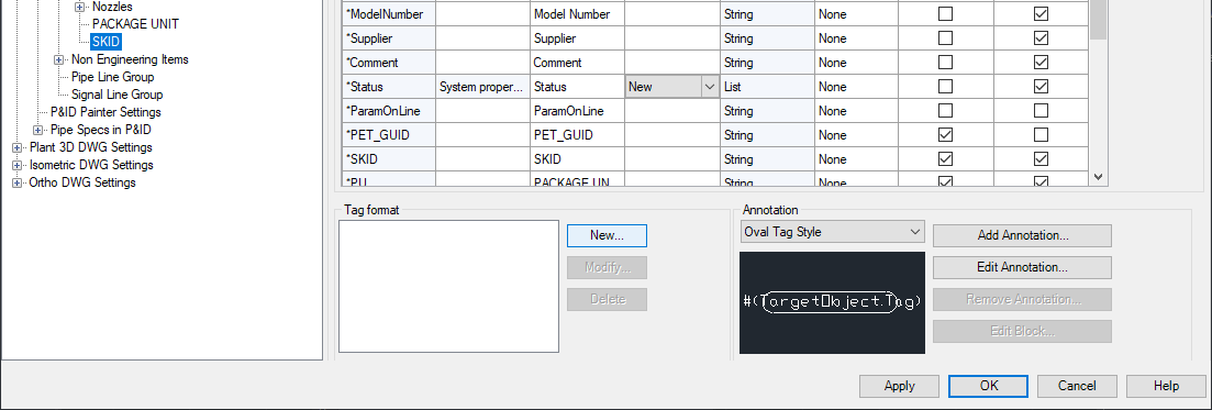
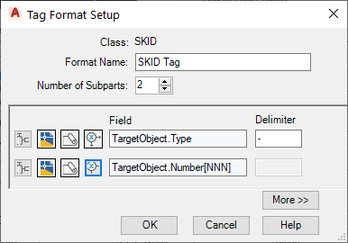
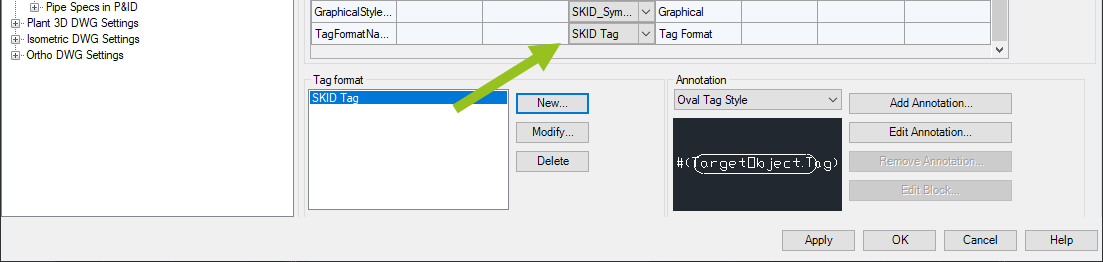
Then we click on the "New..." button to define the Tag Name Format.
We use Type and Number as the two properties.
Make sure that the new Tag Format is set under TagNameFormat.
For the PACKAGE UNIT class we set the Layer and Linetype. The color will be calculated, so we don't need to set it.
We also need to set the color in the block to ByBlock.
Usage
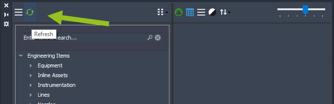
In order to insert the new Assembly classes we Refresh the SymbolsPalette.
We insert the SKID Assembly.
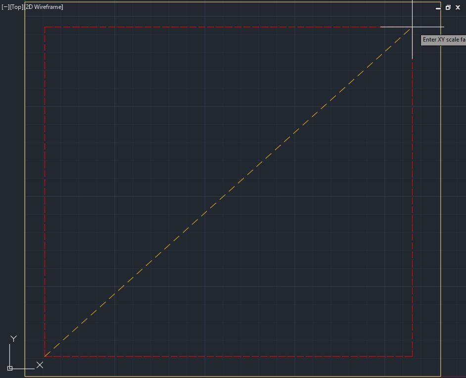
Since Type has a default value of 'SKID' we only need the number.
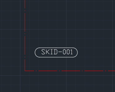
If needed you can annotation too.
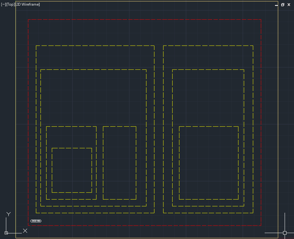
Then we insert the first level of PACKAGE UNITS Assemblies. Because of the calculation the Assemblies will be colored in Yellow.
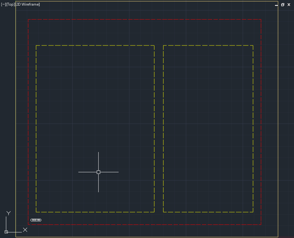
Then we insert some more.
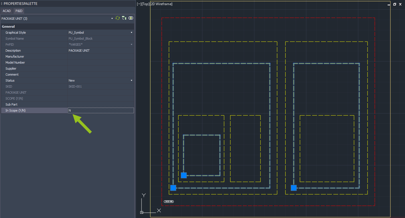
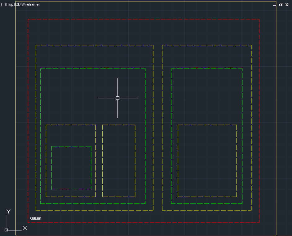
We select the second and fourth level Assemblies and set them to 'N' for the Scope.
After the Scope values has been changed, these Assemblies will now become green.
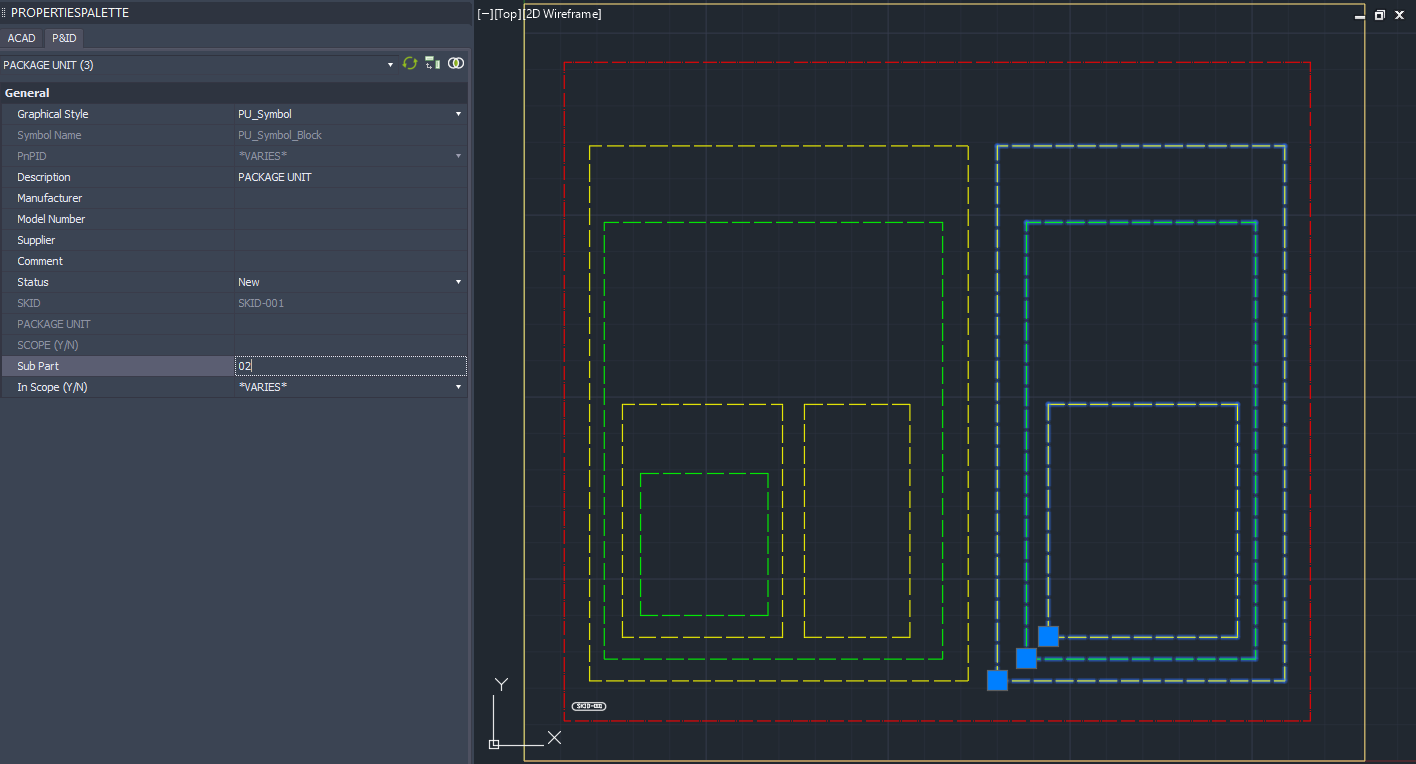
Next we select all the PACKAGE UNIT Assemblies on the left and type in '01'.
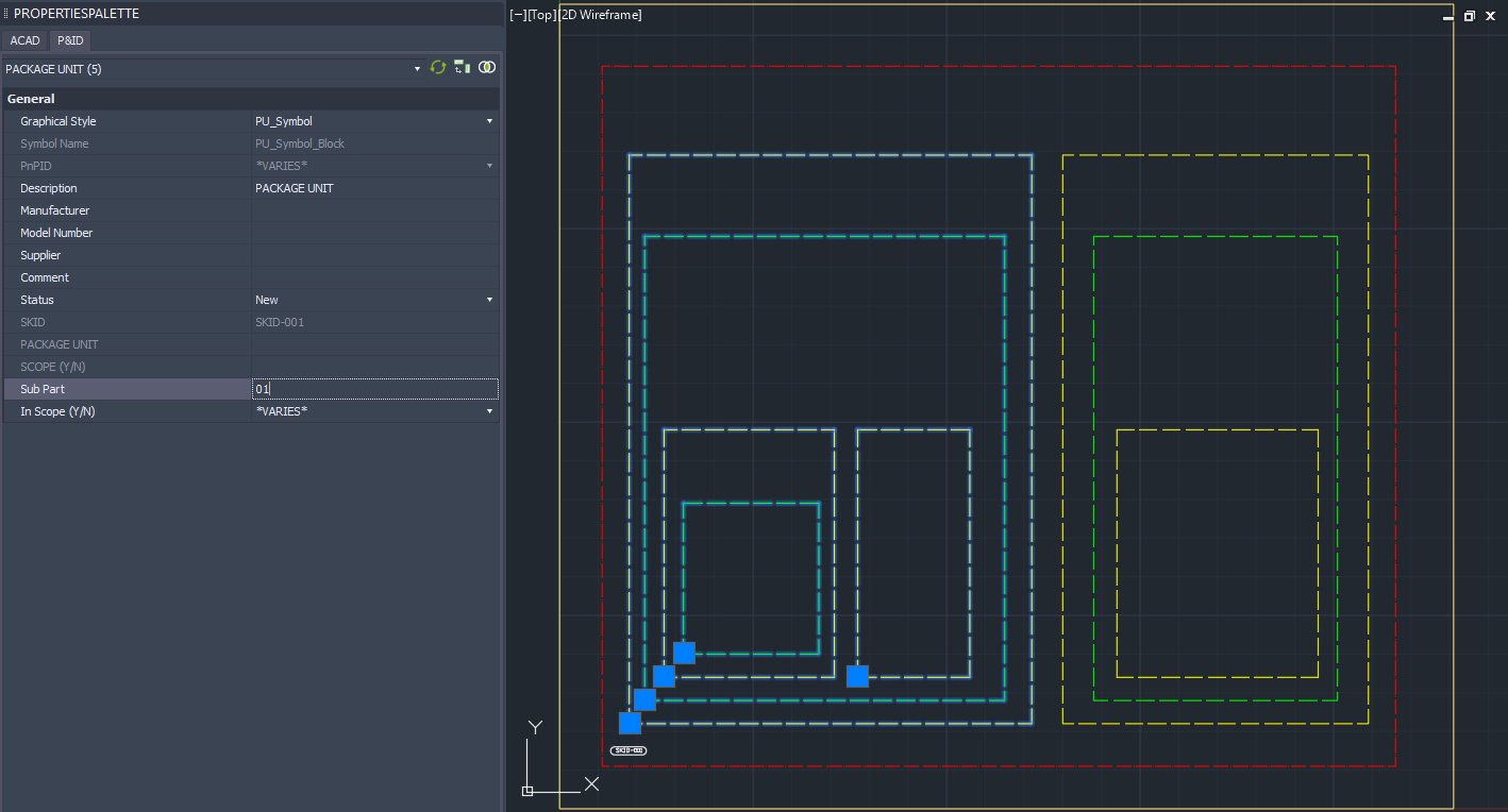
On the right we use '02'.
Then we insert symbols in each level.
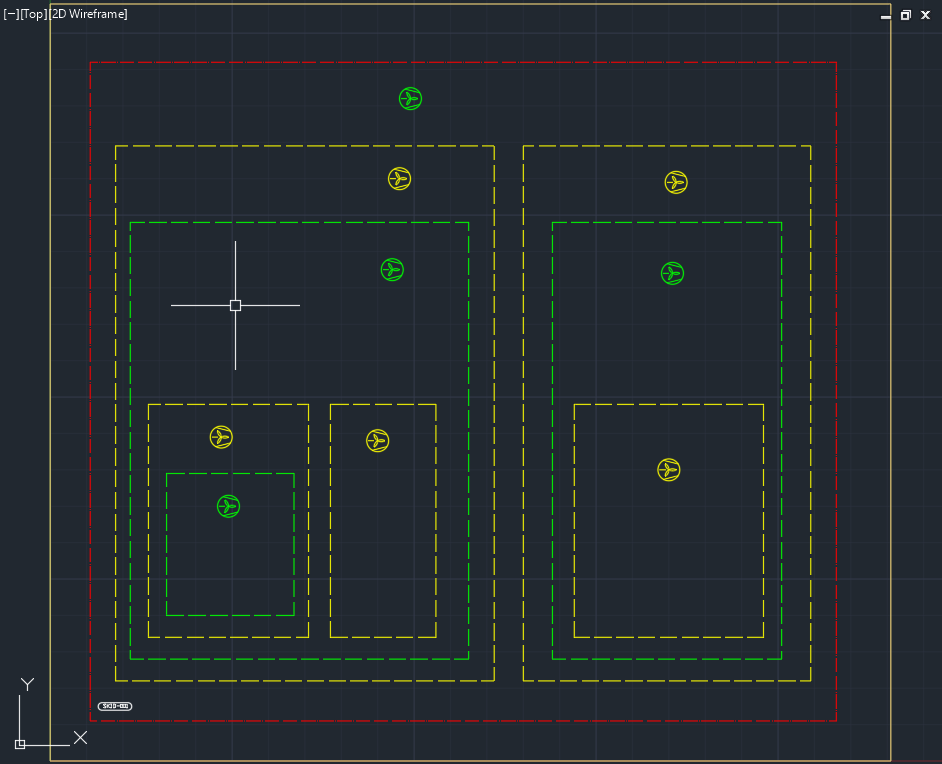
Because of the second calculation the symbols will be colored as soon as they are inserted.
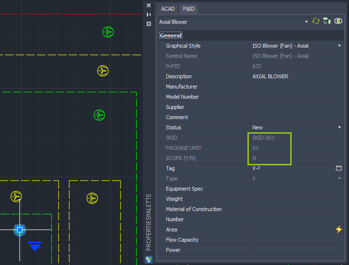
Now we have a look at the properties to see what the mapping of the properties did.
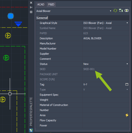
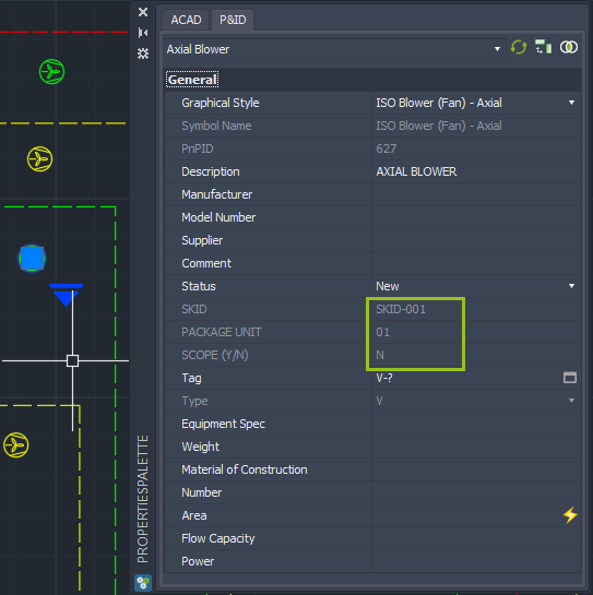
The symbol which is outside every PACKAGE UNIT shows the SKID Tag under SKID.
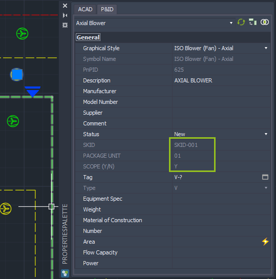
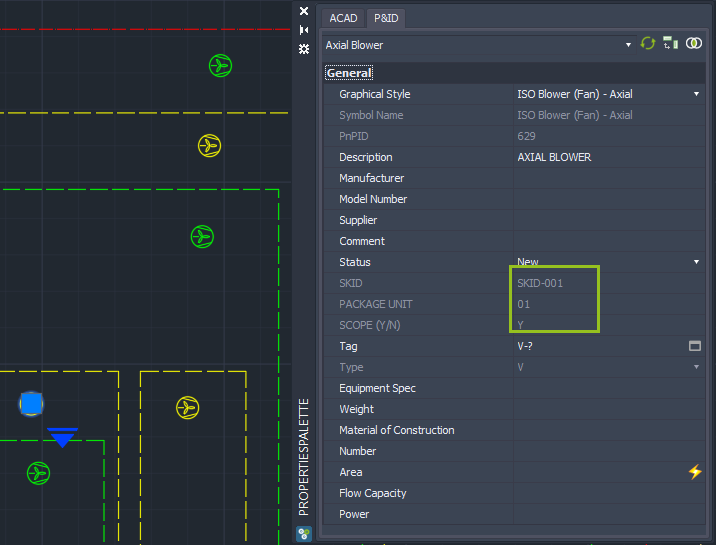
The next symbol also shows the PACKAGE UNIT number and the Scope.
The next one shows the Scope is 'N' coming from the Green Assembly.
The next inner level is showing 'Y' again.
And the most inner one is set to 'N' again.