|
<< Click to Display Table of Contents >> Bolt Parts |
  
|
|
<< Click to Display Table of Contents >> Bolt Parts |
|
Under Revision
The chapter explains how you manage the Bolt parts of the Bolt Catalog.
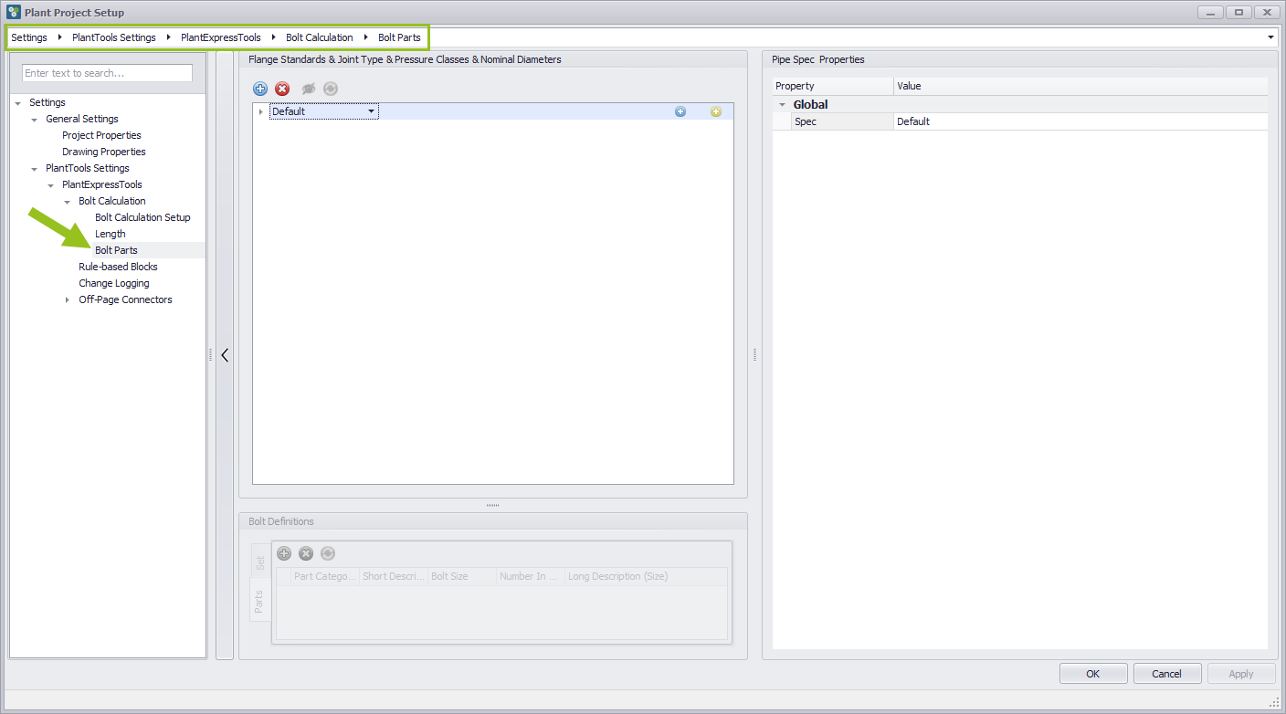
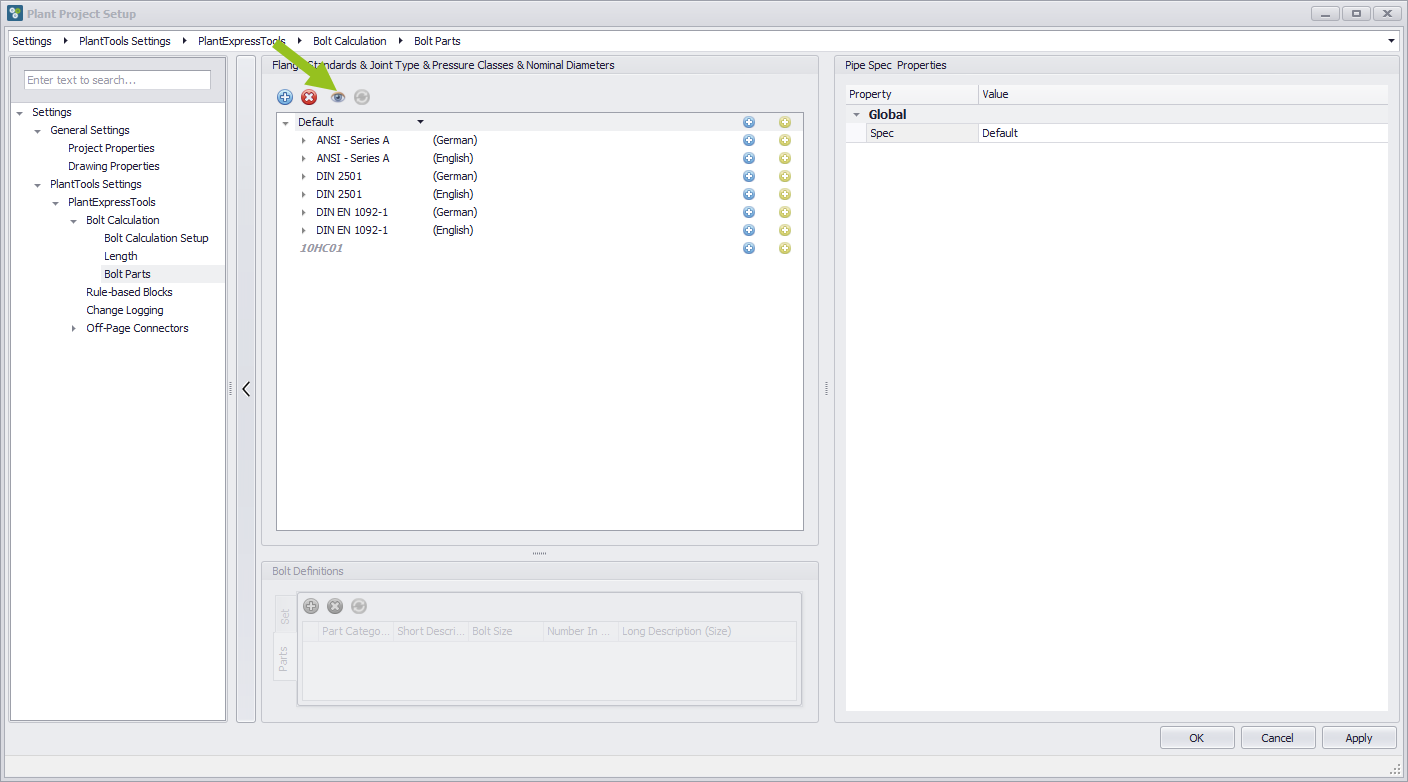
Select Bolt Parts
Click on the Bolt part entry in the left column. A default catalog appears in the middle column. You can see the path in the brower at the top of the path status bar.
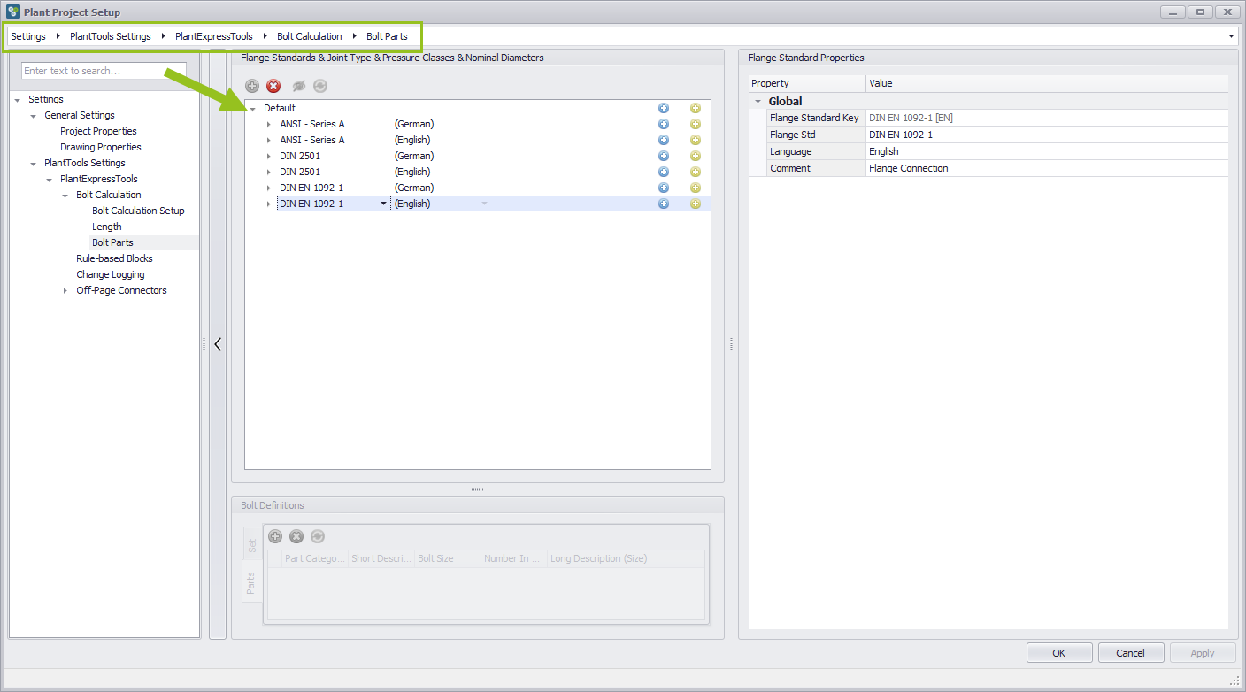
Open default Bolt Part catalog
Click on the open arrow in the Default Pipe Spec line to get a list of flange standards. The flange standards are provided in English and German.
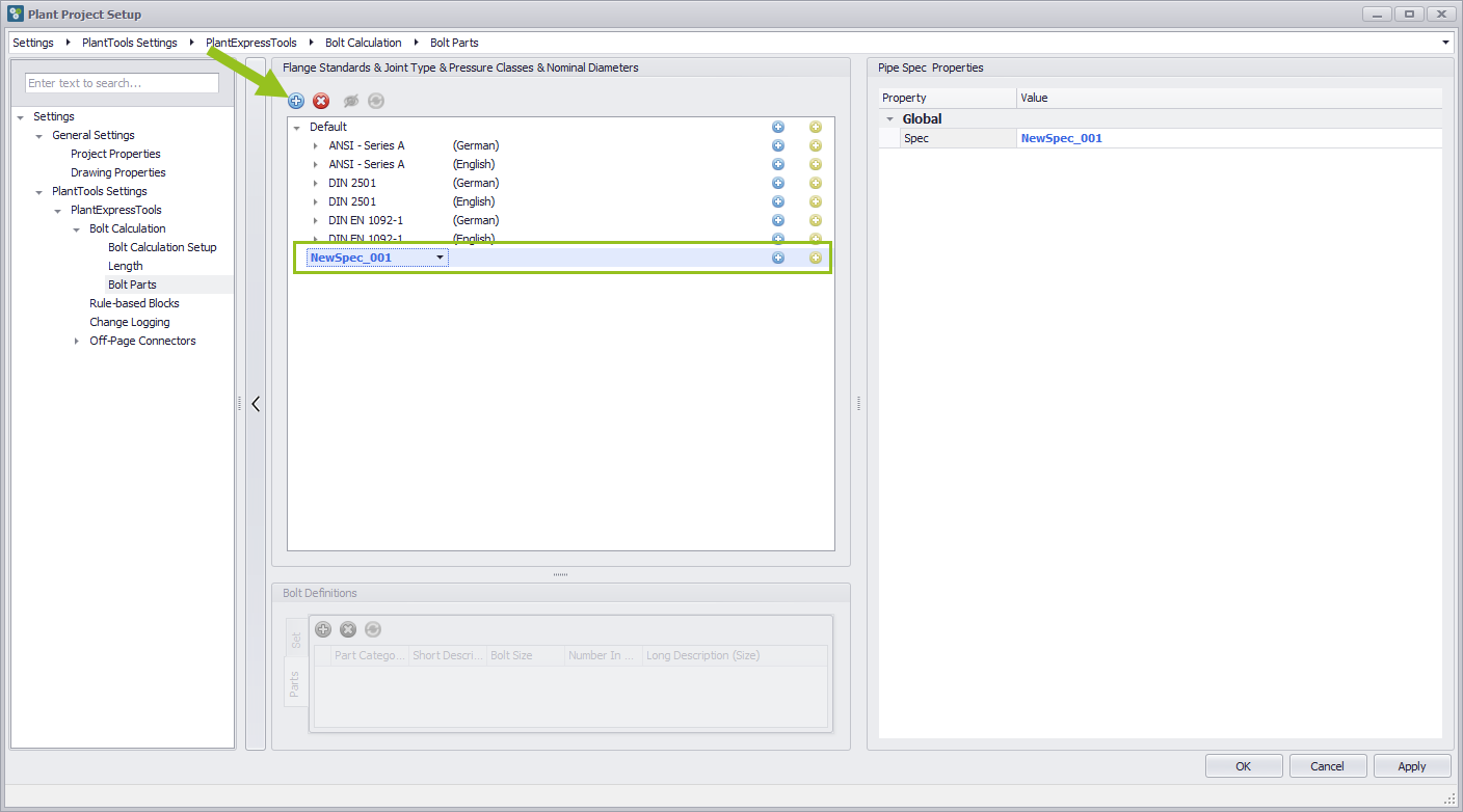
Add a new Pipe Spec
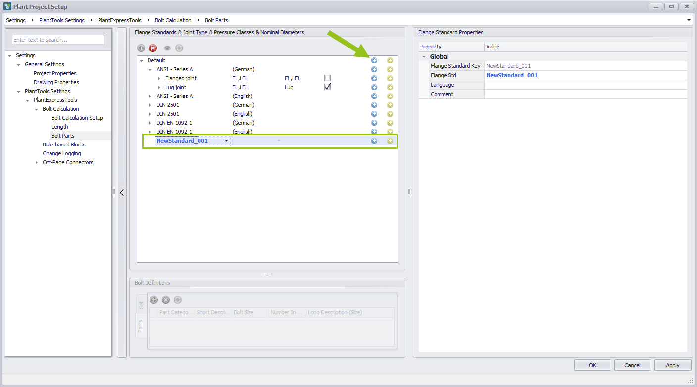
It can always happen that you need an individual Pipe Spec. To create a new Pipe Spec press the Plus button to add a new Pipe Spec. A new entry with the name NewSpec_001 appears, which can either be overwritten or a predefined name can be selected from the drop-down menu. The name can also be selected from the Global Properties in the right column.
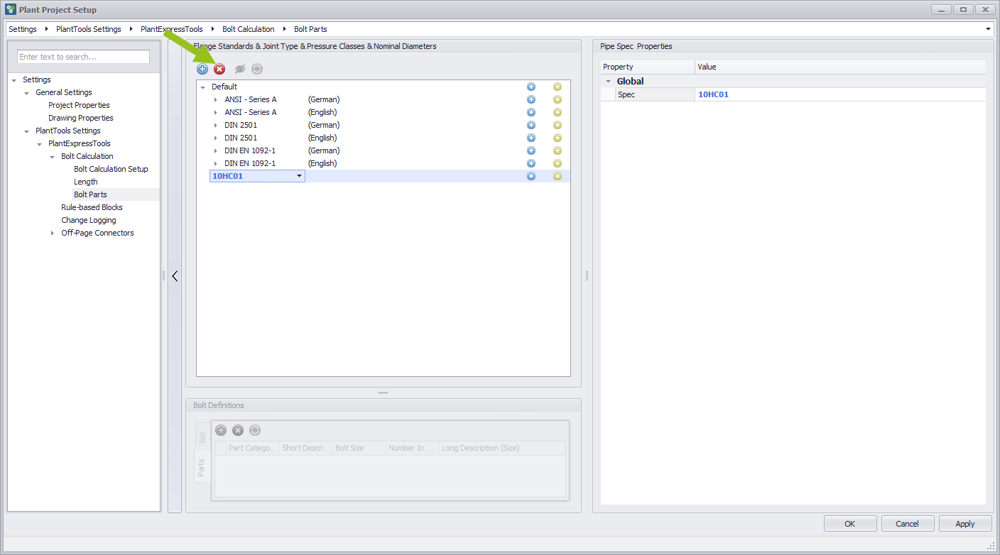
Delete the selected Pipe Spec
If it becomes necessary to delete a created Pipe Spec, then the red Delete button must be pressed. A moderate calculation of the database is the consequence and the entry disappears. The entry is finally deleted when the OK button or the Apply button is pressed.
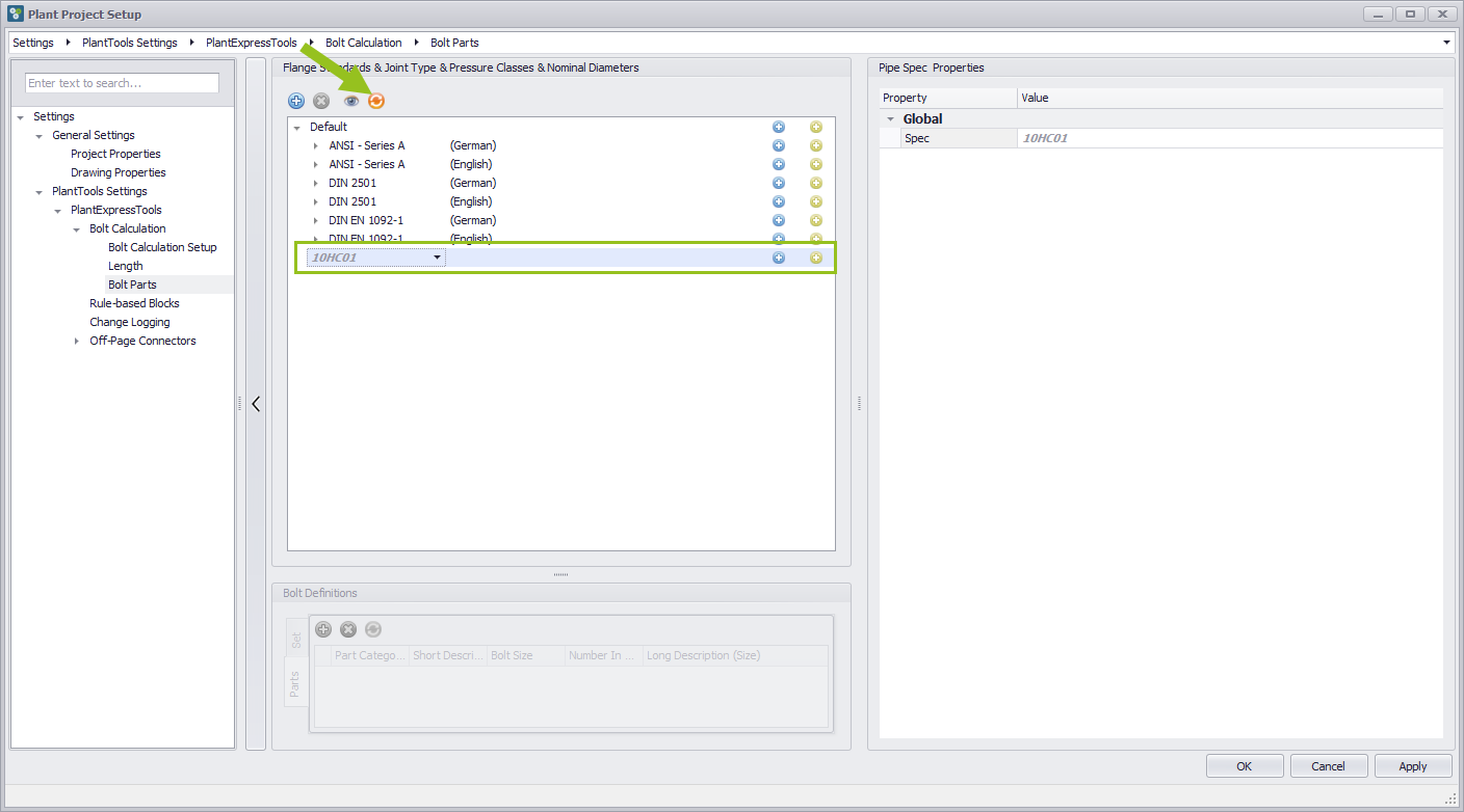
Show/Hide Bolt Spec marked for deletion
It can happen that you remove something by mistake. If the Apply button or the OK button is not yet pressed, it is possible to get the entry back. However, this entry must first be visible.This can be done with the Show/Hide Bolt Spec marked for deletion button. The previously deleted entry is now grayed out but visible.
Restore Pipe Spec marked for deletion
If the deleted entry is grayed out, the Restore button is available. By pressing this button, the previously deleted entry is available for use again.
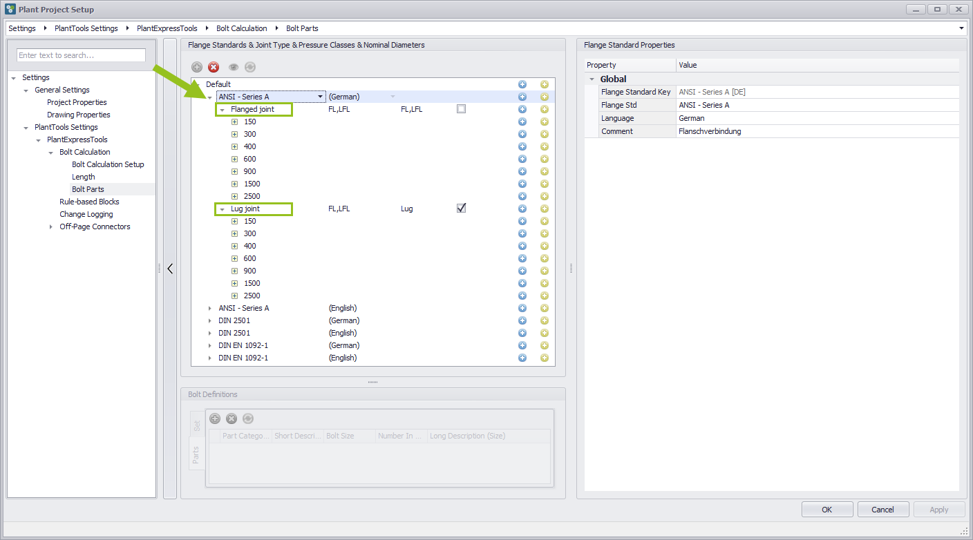
Open flange standard category
When the Plant Project Setup dialog box is opened and the Bolt Parts section is selected, the Flange Standard headers are closed.To access the contents, click the Open arrow on the left. Now Flange Connection and LugTo access the contents, click the Open arrow on the left. Now Flange Connection and Lug are displayed, the contents of which can be accessed by clicking the PLus button to show the Nominal Pressure entries. These also contain information, which can also be opened by clicking on the Plus button. Only then can you see the Nominal Diameter.
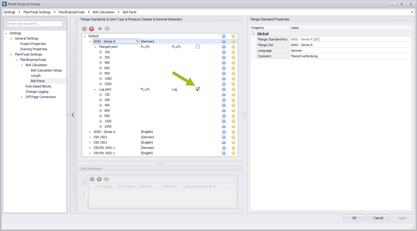
Definition that it is lug
To define that the category is Lug, activate the check box on the right.
Add a new Flange Standard
The Default Pipe Spec already contains several Flange Standards. However, to create a new, individual flange standard, click the blue plus button on the right side of the default line. A new entry with the name "NewStandard_001" is created, whose name can either be selected from the drop-down menu of the entry field or you can overwrite it with your own name.
Copy as a new Pipe Spec
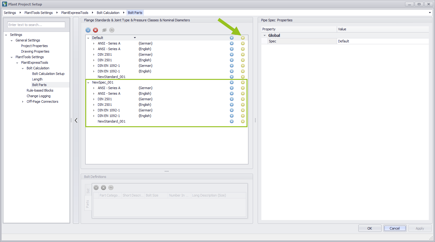
The Default Pipe Spec is usually sufficient for the work in Plant3D, but it can always happen that an own Pipe Spec is required. In order to avoid having to create the contents for this new Pipe Spec piece by piece, the Default Pipe Spec in the database can be copied completely in order to generate a new Pipe Spec from it. To do this, press the yellow plus button in the Default line. A completely new entry is created under the name NewSpec_001, which can be named from a list of Pipe Spec via the drop-down menu or you can decide for an individual name, which can be overwritten in the entry field.
Rename default Pipe Spec
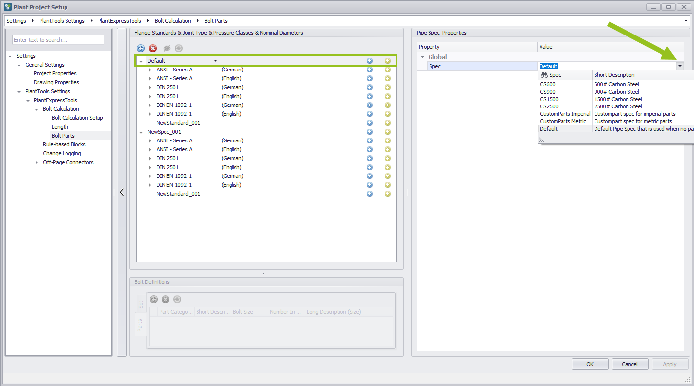
You have the possibility to choose an individual name in the middle area of the dialog box "Flange Standard & Joint Type & Pressure Classes & Nominal Diameters", but you also have this possibility in the right area of the dialog box "Pipe Spec Properties" by selecting an existing name from the drop-down menu or simply overwriting it.
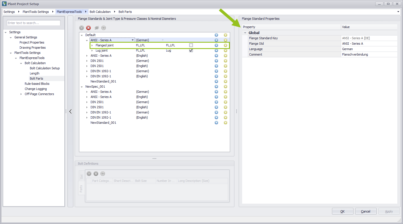
Rename Flange Standard
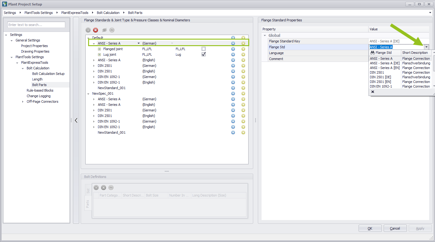
If you have selected the respective flange standard, you will see several lines on the right side in the Pipe Spec Properties, whose name you can overwrite or change via a drop-down menu, which has an effect on the entries in the middle area of the dialog box. In the line Flange Std you can change the name of the Flange Standard.
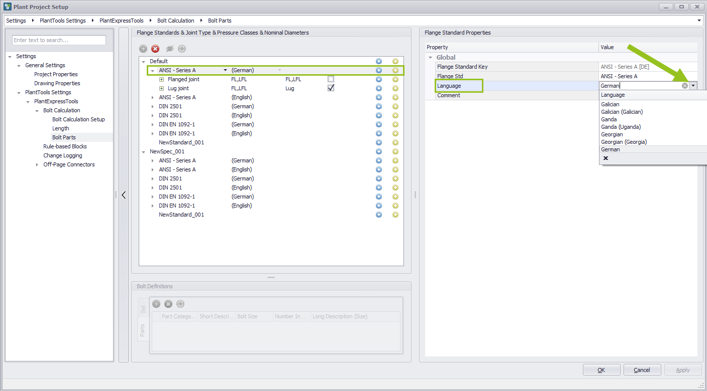
Change language of Flange Standard
The language can also be changed in the Language line via a drop-down menu.
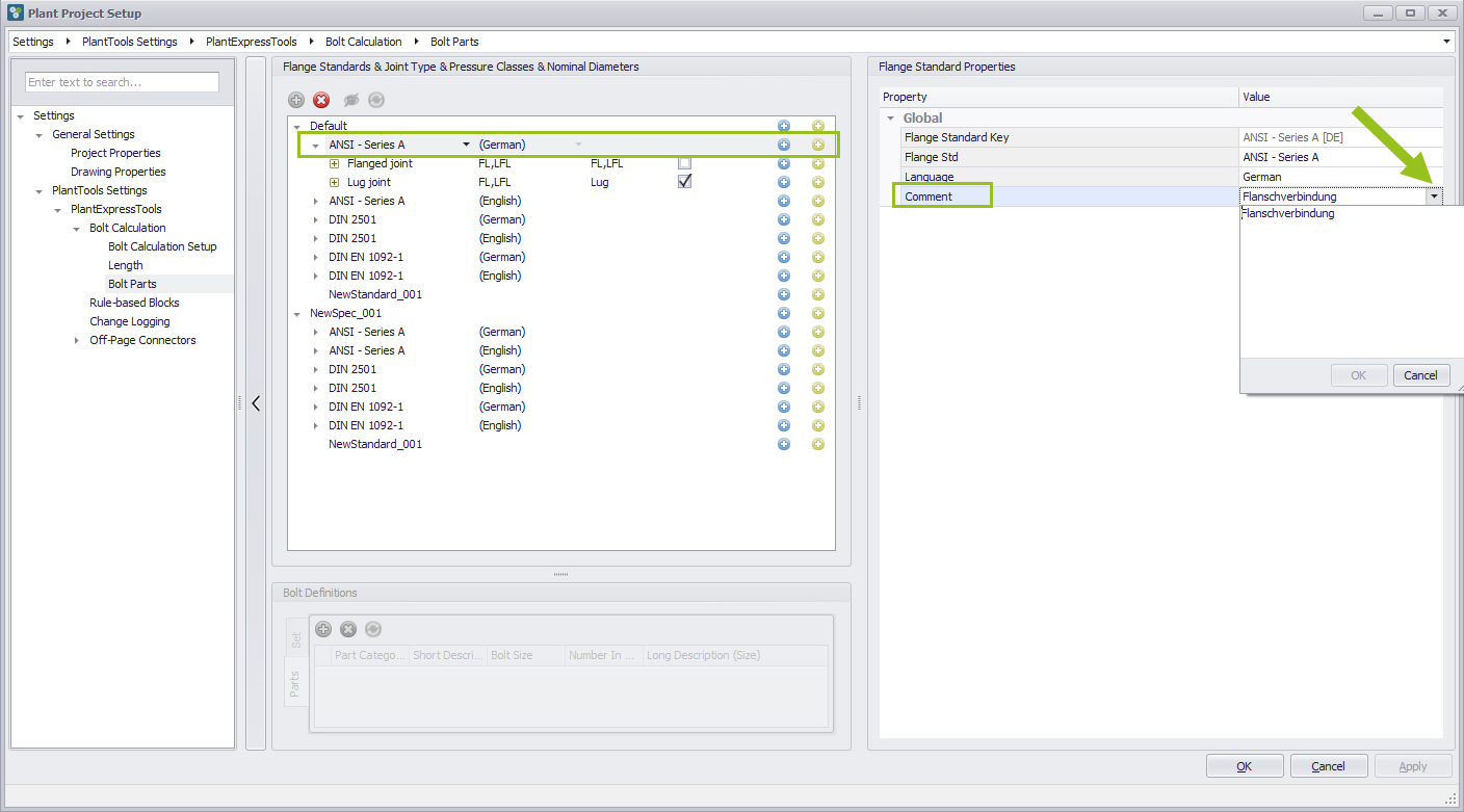
Add a comment for Flange Standard
Furthermore, a write field can be activated in the comment line via the dropdown arrow, in which a long text can be entered.
Global information about the connections of the Flange standard
If a Flange Standard is selected from the Pipe Spec and the Joint Type is clicked, the Global Information for the entry is displayed on the right side in the Connection Properties area.
View connections of the Flange Standard
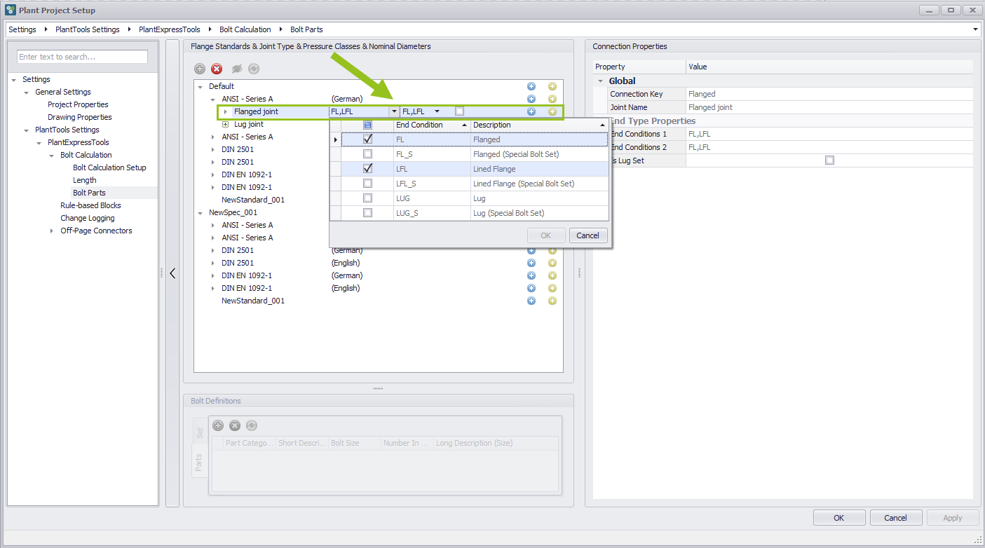
Normally the user expects that the connection types can be changed. However, if a Pipe Spec is created, the system gets the information from another configuration area, so that nothing can be changed here via the available drop-down menus, but only viewed because the entries are grayed out. So in the middle area you see three columns, of which the first and the middle column deals with the connections. the right column again describes the fact whether it is Lug or not. On the right side you can also see the corresponding connections in the End Type Properties area. The End Condition 1 and End Condition 2 fields are drop-down fields from which you can select the desired connection.
In short, the lists in the dropdown menus show all simple connections from the Plant 3D setup where both connections have an end code defined as "Flanged".
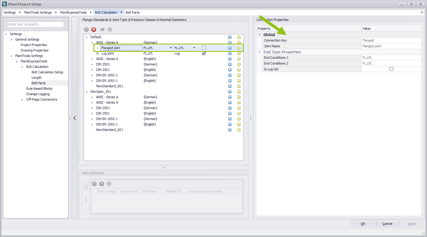
In the middle area there are also drop-down menus that contain the same information as the one on the right.
Global information about the connections of Lug
The category "Lug connection" is similar to the category "Flange connection". Here one end condition is a Lug and the other is a flange. Therefore, the checkbox is activated at "Is Lug Set".
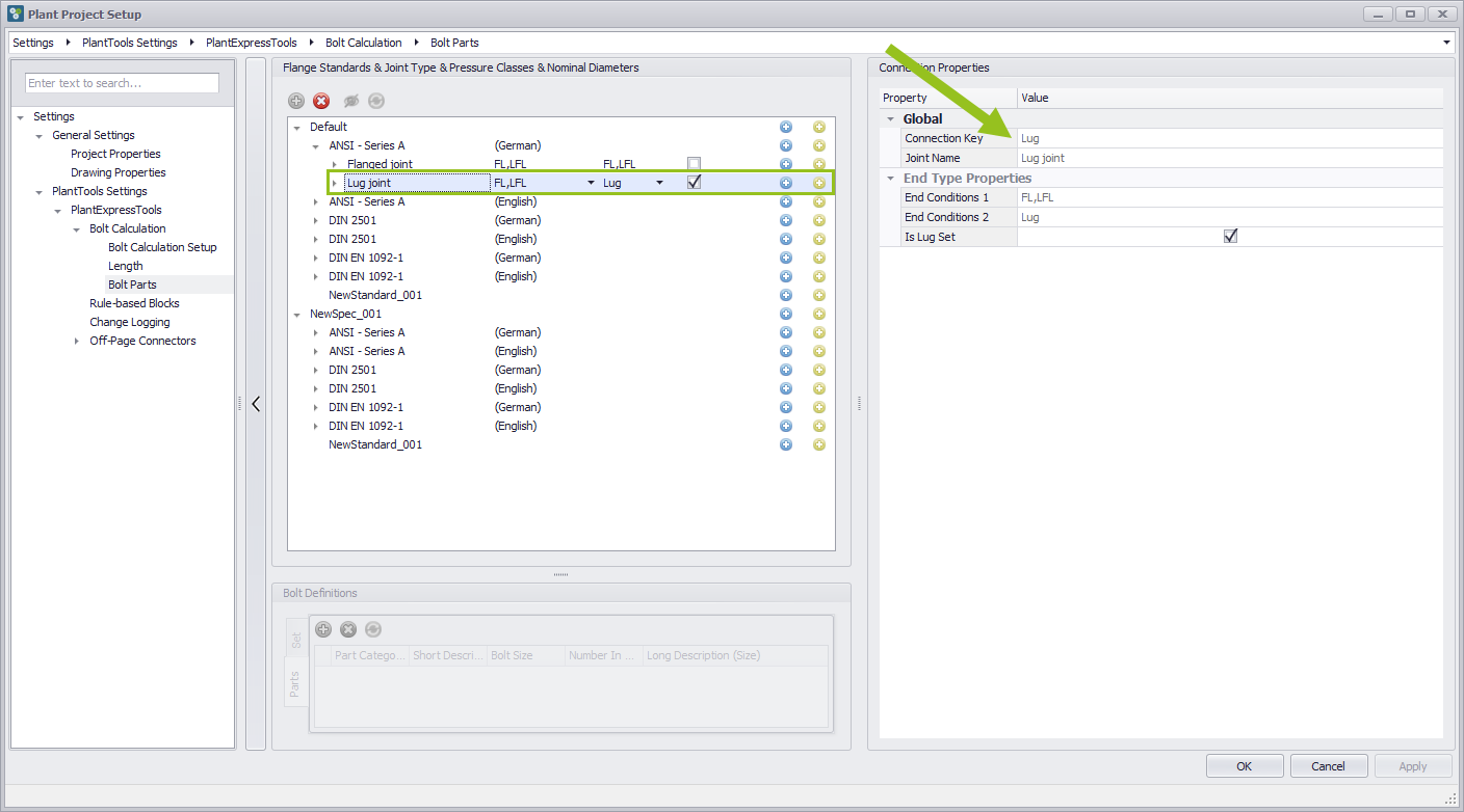
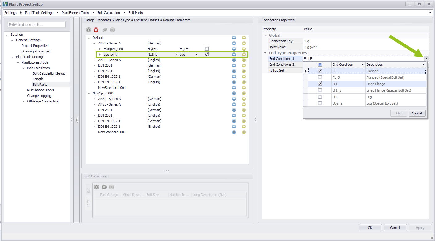
View connections of Lug
Theoretically, the fields End Connection 1 and End Connection 2 could be changed using the drop-down menu, but the entries are grayed out, so this is not possible.
Open nominal pressure category
To see the entries of the pressure ratings, click on the plus icon. The corresponding list opens. After this category has been opened for the first time, an open arrow is available.
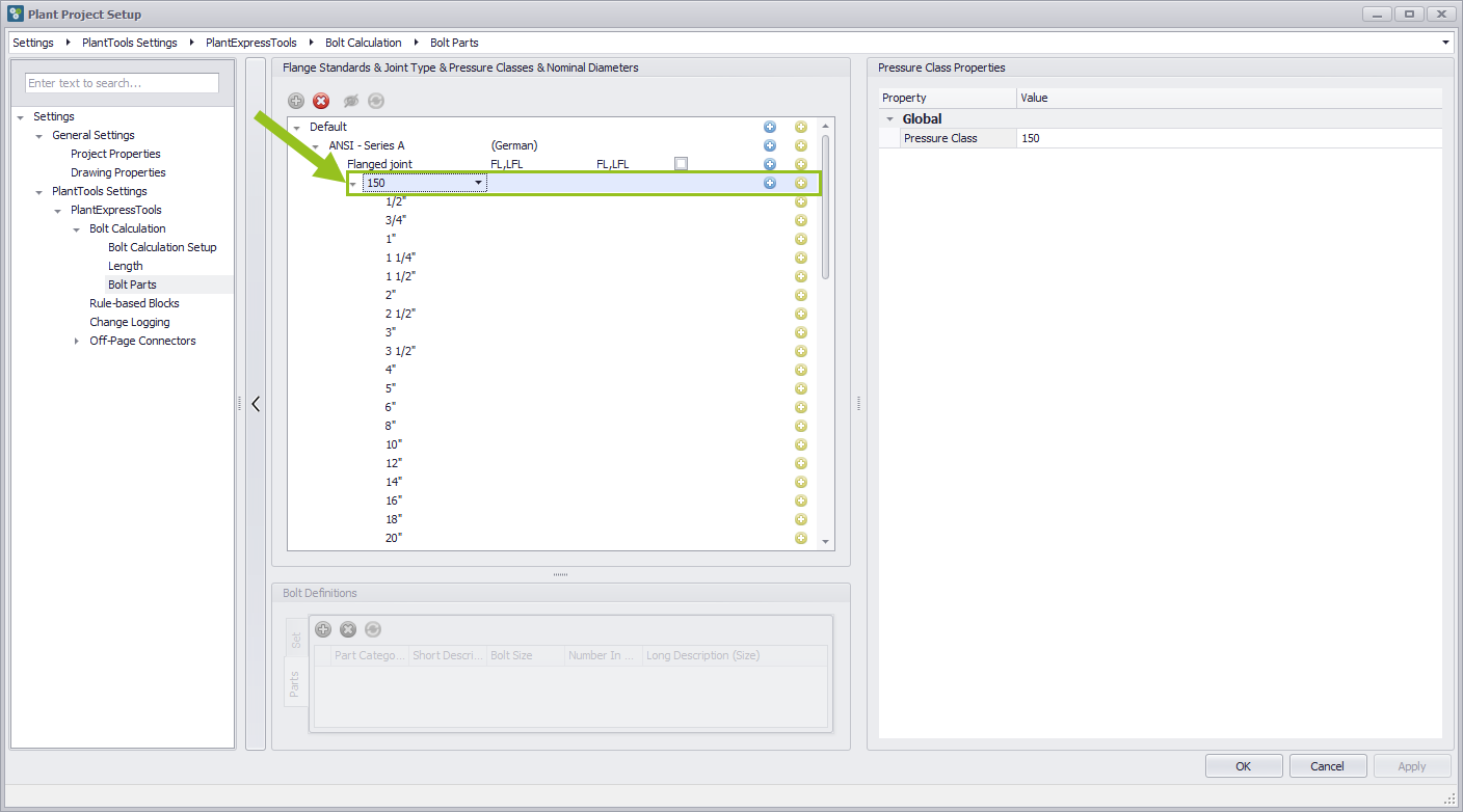
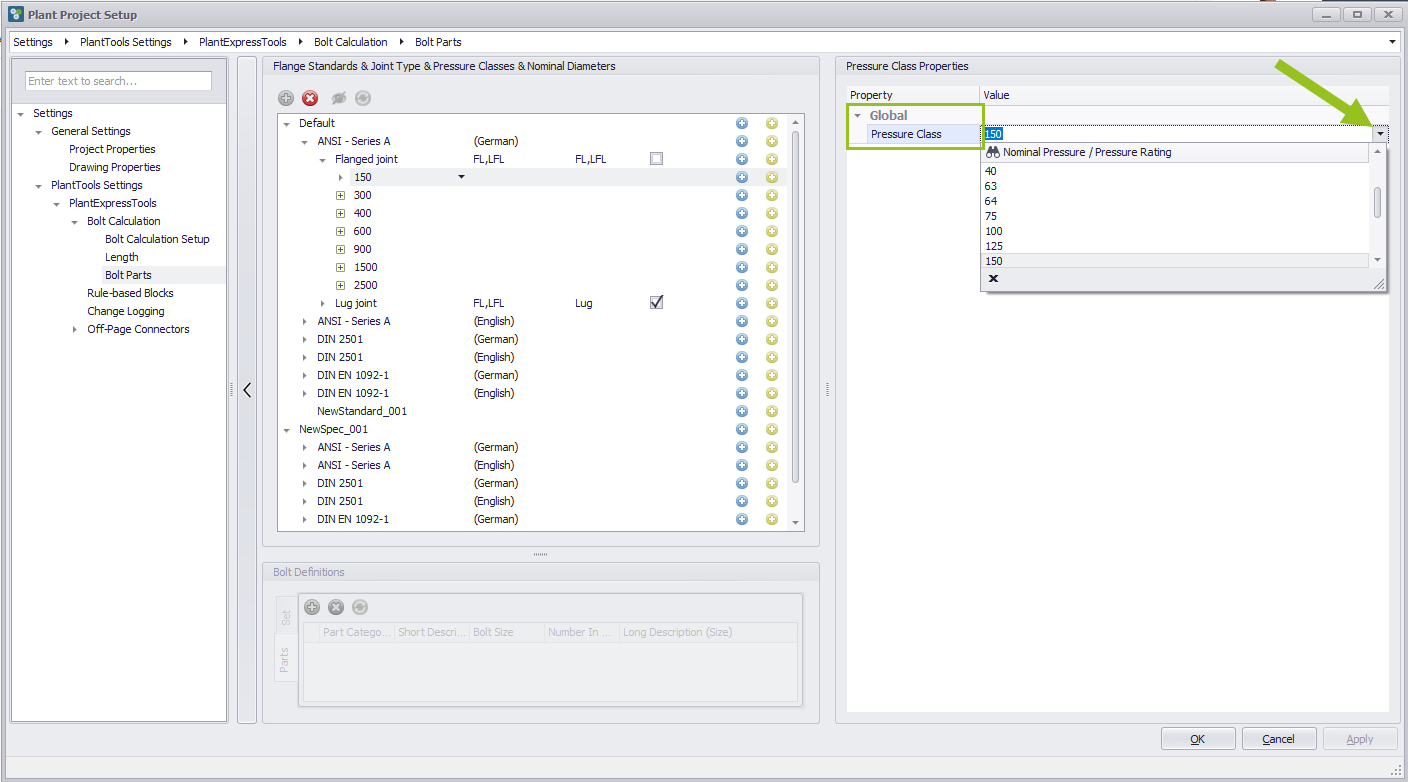
Global information about the pressure class
If you have selected a Nominal Pressure entry from the Flanged joint category, the Global Properties of the Pressure Class are displayed on the right-hand side. This entry can be selected, adjusted or overwritten via a drop-down menu.
Nominal diameter
To see which nominal sizes are assigned to the pressure stage, open the drop-down menu. Three columns are visible here. On the left the actual nominal diameter, in the middle the nominal diameter value and on the right the nominal units. By selecting an entry from the drop-down list, the preset value can be changed.
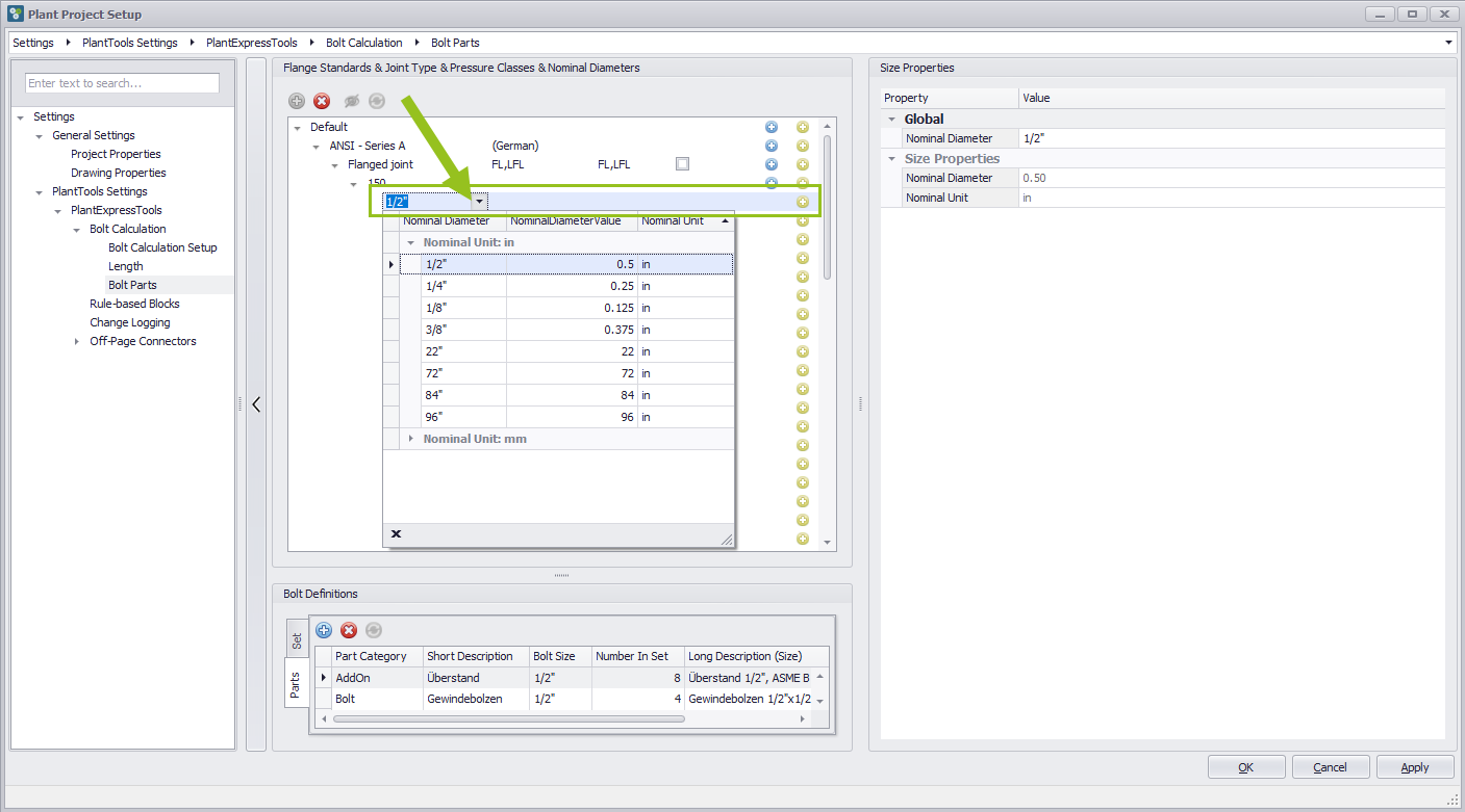
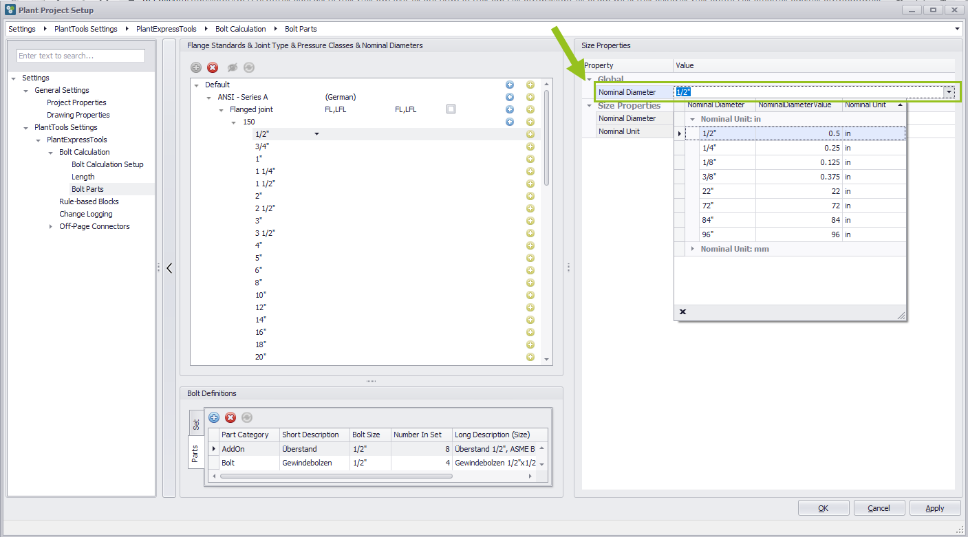
Global information about nominal diameter
All entries and changes can also be reviewed on the right side under Global Properties in the Nominal Diameters field. In addition to the inch as the default unit, millimeters can also be selected.
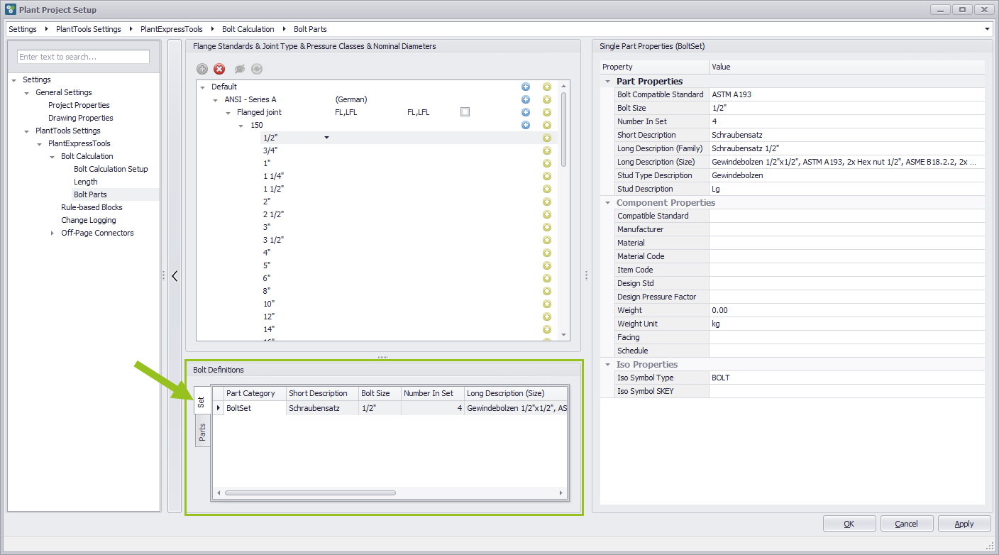
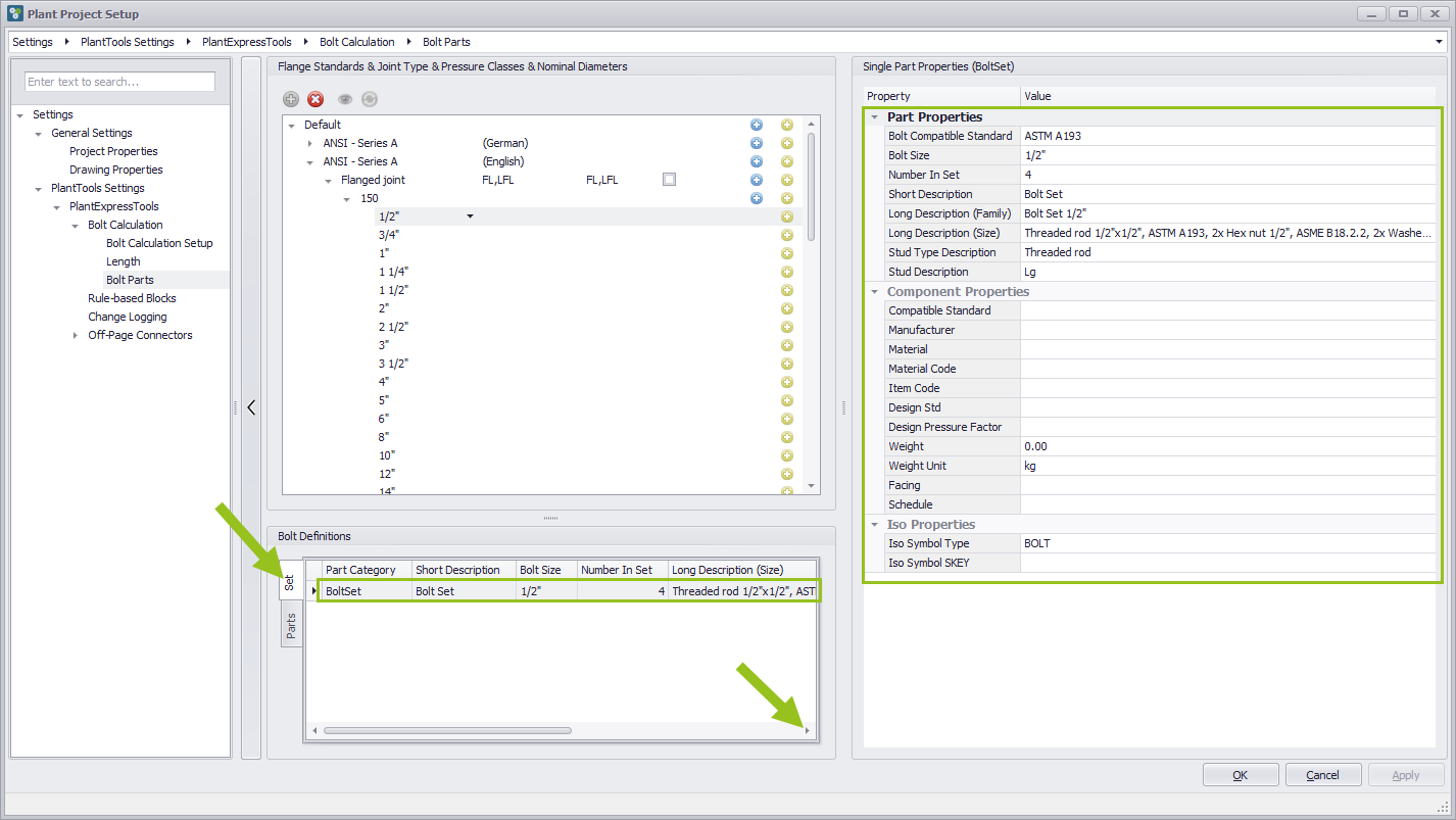
Bolt definition
When a nominal diameter has been selected, you will see the information about the bolt definitions in the middle column at the bottom, which is divided into bolt sets and bolt parts via two tabs. While you can access the caterogies of the individual components in the Bolt Parts and add or delete additional lines for component definitions, this feature is not available in the Bolt Sets.
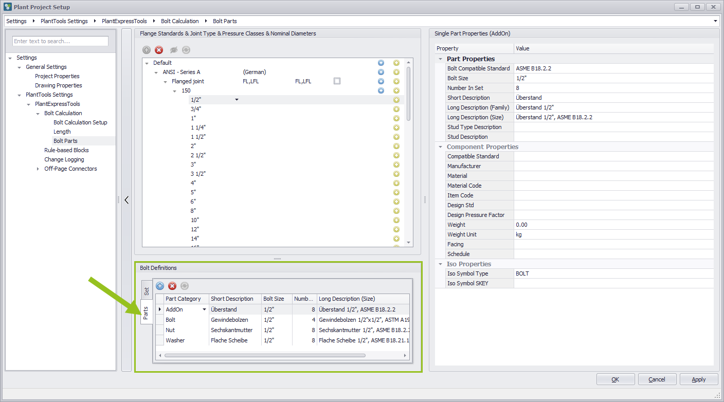
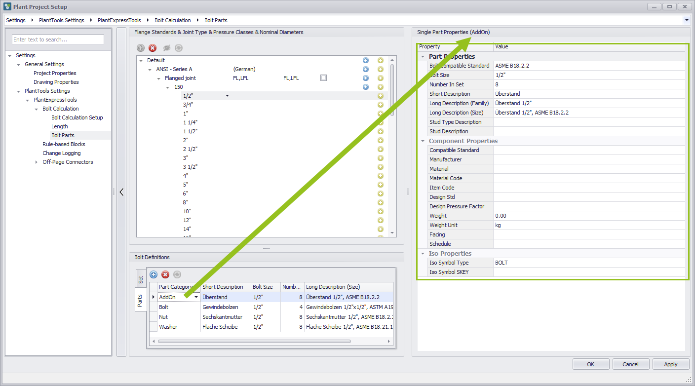
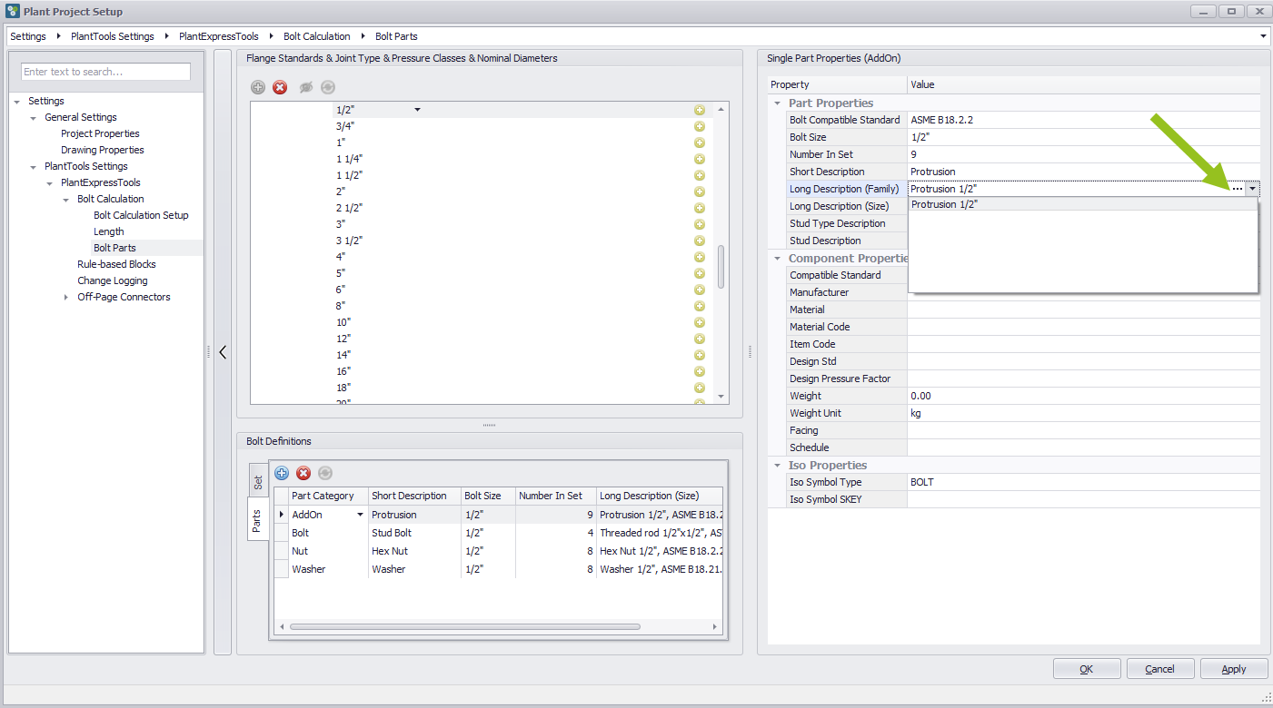
Single part properties (AddOn)
On the right in the Single Parts Properties you can see the respective recorded information for the Single Parts Addon, Bolt, Nut and Washer. Depending on which line you have selected in the middle column for Bolt Definitions, the information for the corresponding part can be edited separately.
The following procedure for the Bolt, Nut and Washer lines is identical to that for AddOn.
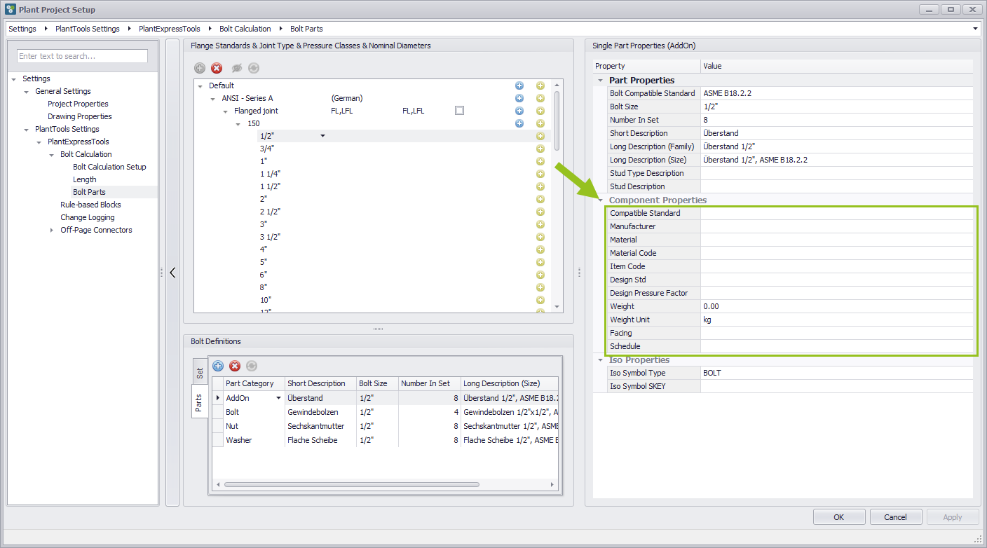
Component Properties
The user can add individual, user-defined data entries to the 11 fields of the Component Properties area.
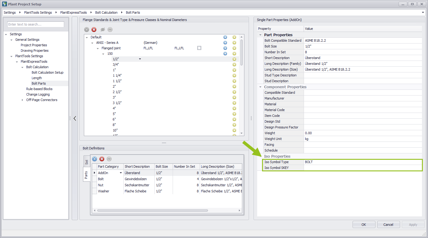
Iso Properties
There are two lines in the Iso Properties section, which always has the entry "Bolt" in the Iso Symbol Type field when setting up the definitions of Bolt Parts. This entry defines which symbol the Isometry module of Plant 3D should use when creating the piping isometrics.
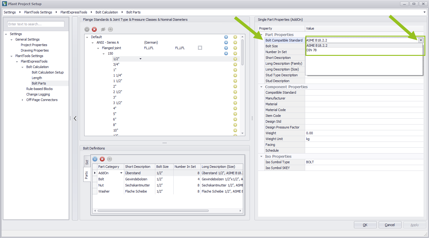
Change Bolt compatible standard
To change entries in the Bolt Compatible Standards row, scroll down the drop-down menu on the right. Two entries can be selected, but not overwritten. The system gets the information which entries are selectable here from the Bolt Length Category.
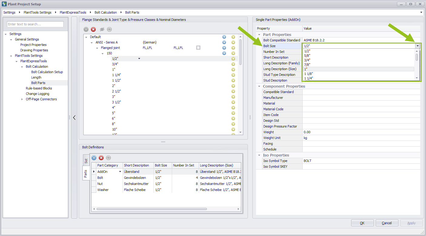
Change Bolt Size
If you want to change the entry for Bolt Size, select the drop down menu on the right side from which you can select the entry that is defined in the AddOn settings for Bolt Length.
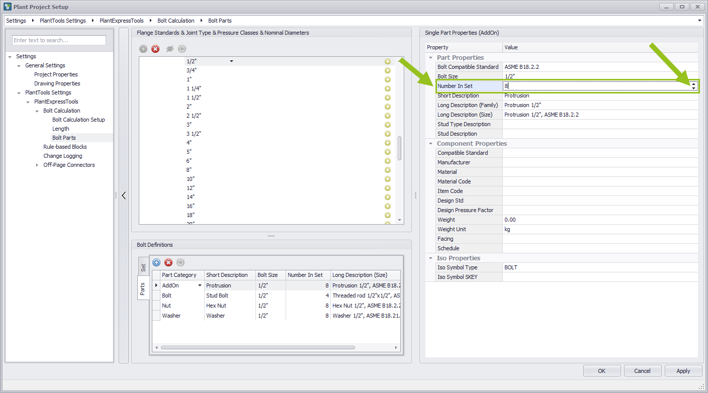
Change Number in Set of Bolts
The number of screws of the flange joint can be changed. To do this, select the UP/Down button on the right-hand side. This changes the number of Bolts in four steps. The number of Bolts can also be overwritten individually. However, a number of screws other than based on 4 screws is unusual.
Area of descriptions
If you want to add free description texts in addition to the settings in the Single Part Properties, you can do so by adding the lines "Long Description (Family), Long Description (Size), Stud Type Description and Stud Description".
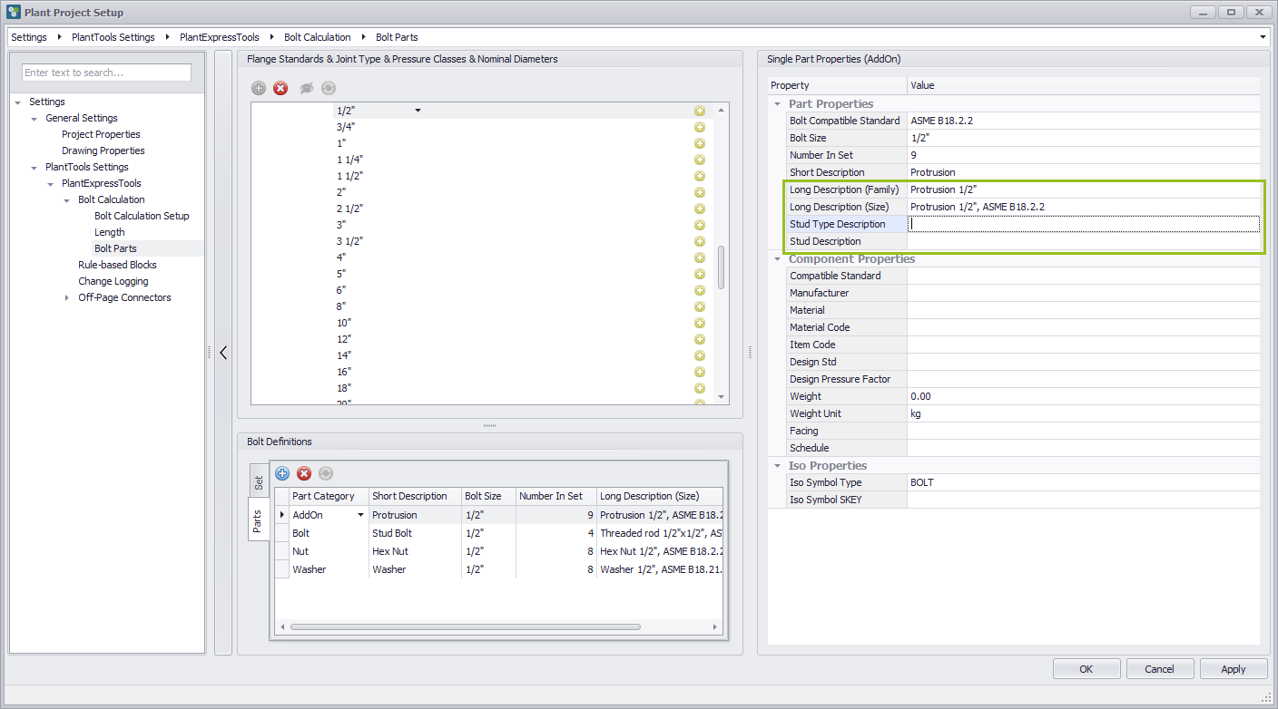
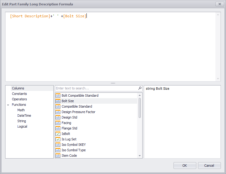
The first two lines provide dropdown menus with the possibility to open another dialog box.
This dialog box represents a kind of description generator, with which one can configure oneself from existing data base parameters error-free a description together.
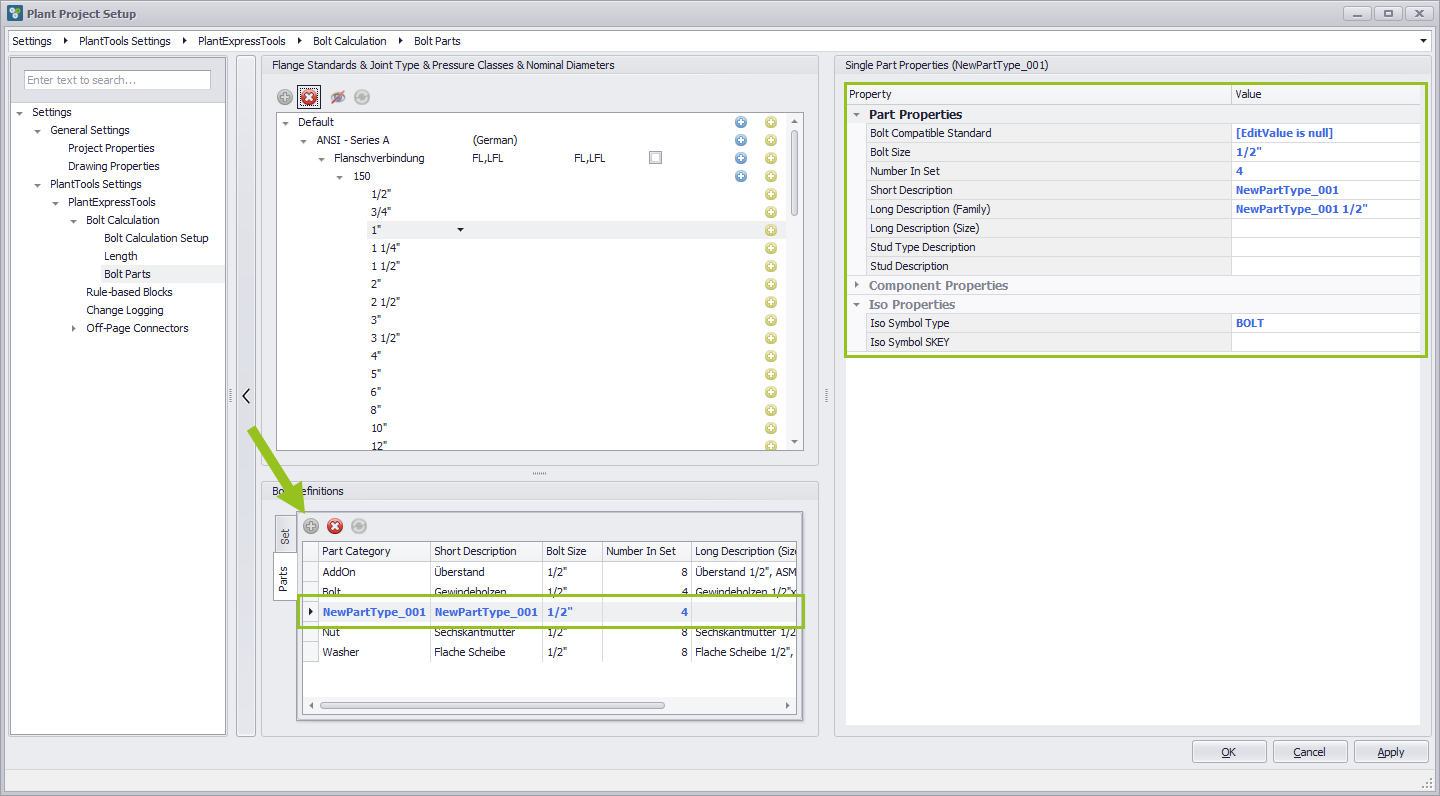
Add a new size definition
If you press the Plus button, a new entry with the name NewPartType_001 appears in the list. However, in the form that this is not particularly useful and also can not be edited. This also applies to the entries in the Single Part Properties on the right side of the dialog box. You have to take another process before.
Preparations to get a new Size Definition
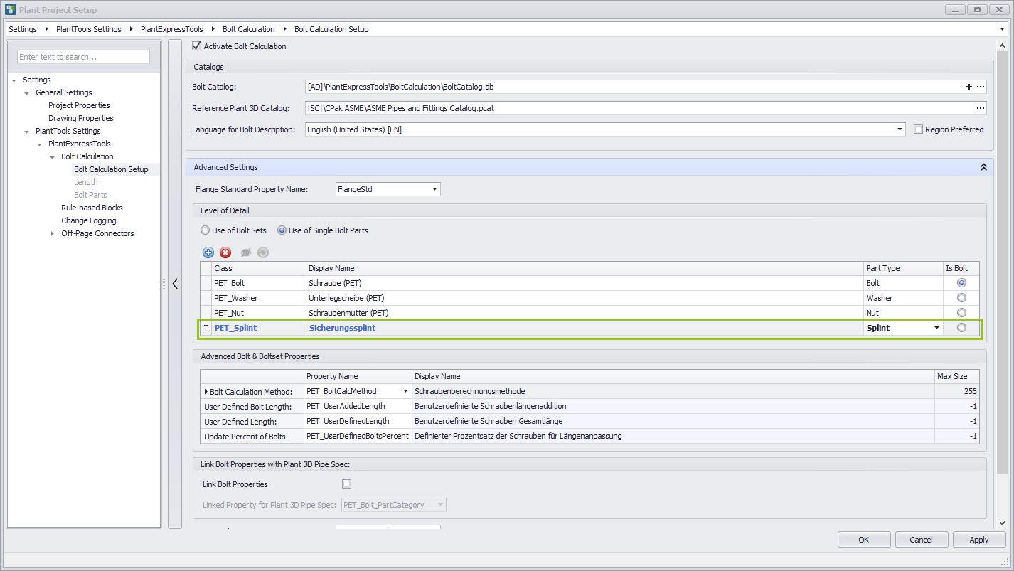
To get a new size definition you have to go to the Bolt Calculation Setup first. There, in the Advanced Settings area, in the Level of Detail section, under the item "Use of Single Bolt Parts", a New part Type is created. A new entry with the name PET_NewBoltPart_001 is created.
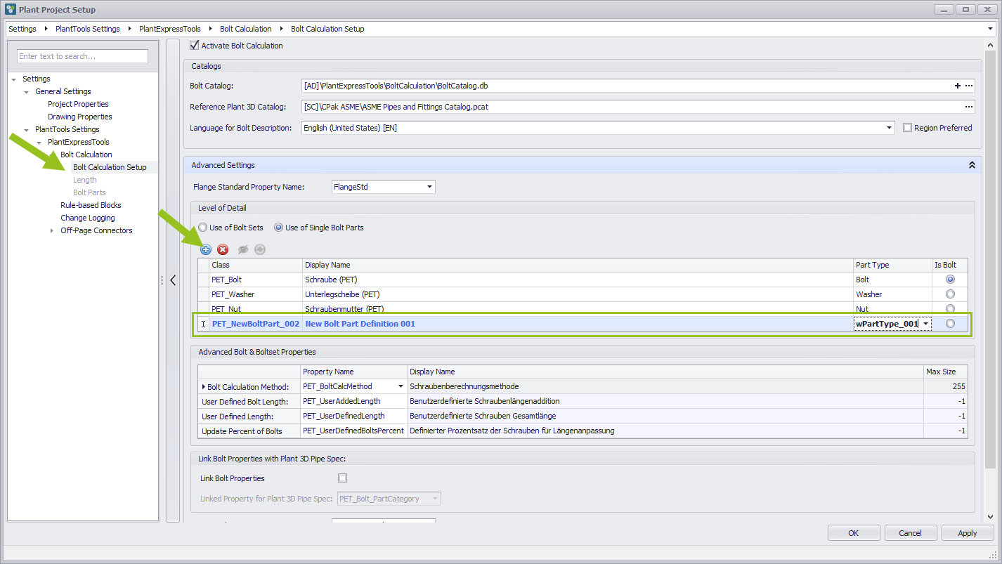
In the newly created row there are four columns, the contents of which can be overwritten user-defined in the first three columns, but can also be operated via a drop-down menu from predefined entries. When the line is set as desired, press the Apply button to write the values to the database. Only then they are available in the Bolt Part category. In addition, the Length and Bolt Parts categories are no longer grayed out, but are displayed in black and can therefore be selected again.
Final process to add a new size definition
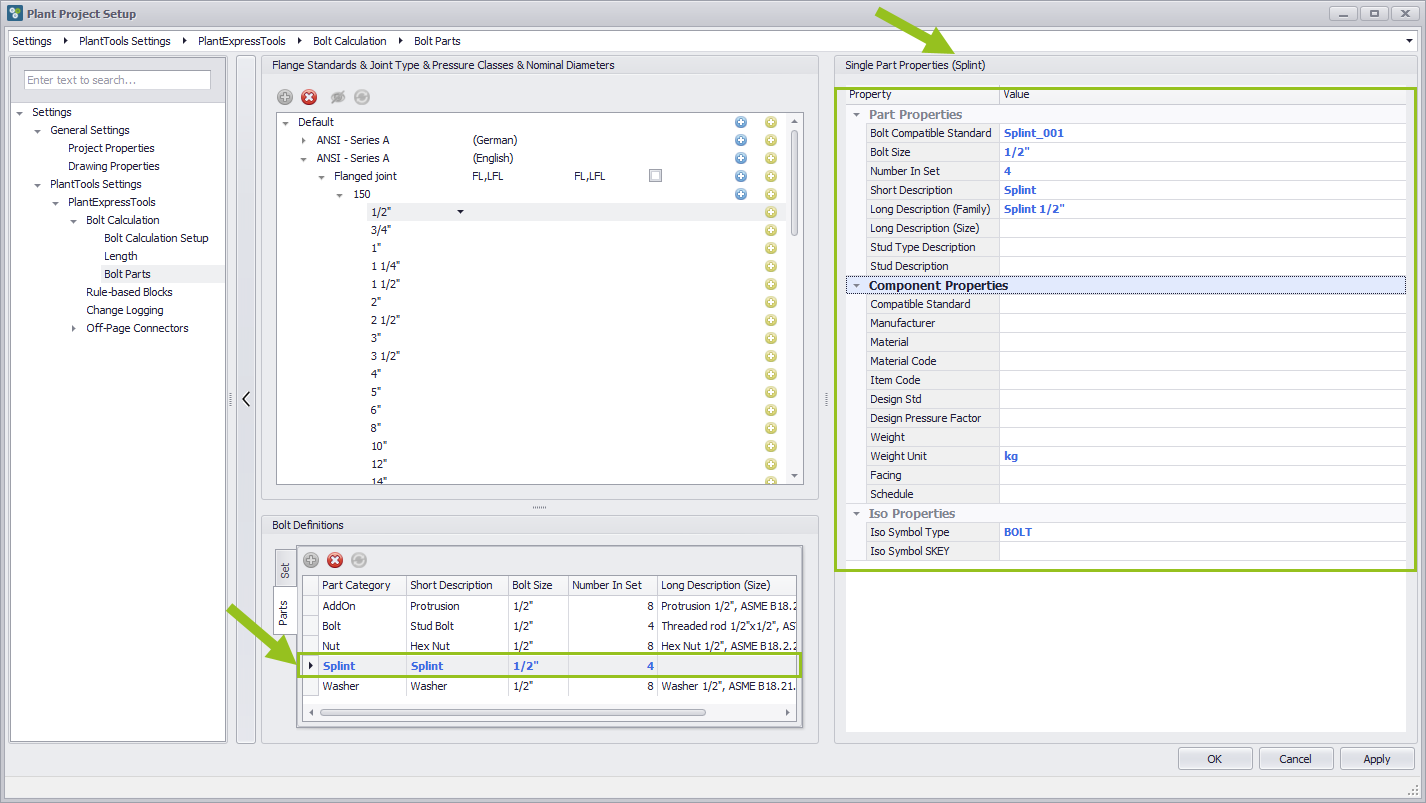
Additional lines can now be added to the Bolt Parts category. To do this, go back to Bolt Parts in the left-hand area of the dialog box and create a new entry in the lower middle area at Bolt Definition using the Plus button, and the part previously added in Bolt Calculation Setup will appear. It is still displayed in blue. You can now make further additions and changes on the right side of the dialog box. If the Apply button is pressed, then the entries are available, as they have then been finally written to the database.
Delete the selected Bolt item
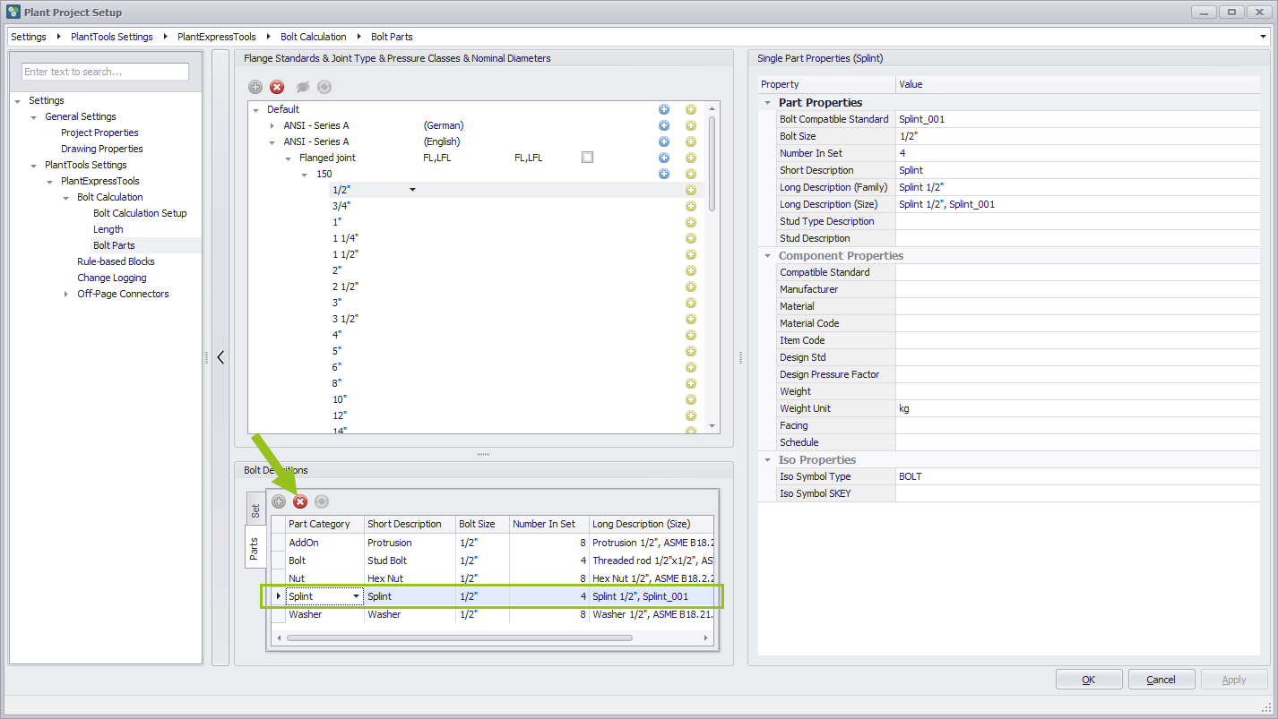
To delete an erroneously created line, press the Delete button. To do this, the corresponding line must be selected. The selected line is no longer visible, but not yet removed from the database. To do this, the Apply button must be pressed.
Restore Bolt item marked for deletion
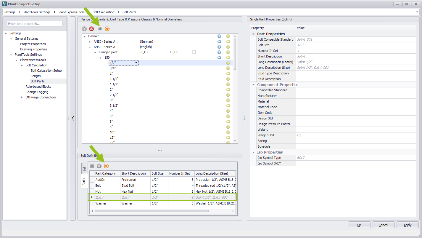
If it should happen that a line was deleted by mistake, this line can be retrieved again. In order to see which entry was deleted before, it is no longer displayed, it must first be made visible again. To do this, press the button "Show/hide the Item marked for delition" in the topmost area of the middle column to make the entry visible. It is necessary to select the button from the upper area, because there is no such button in the lower area. Then press the "Restore the Bolt Item marked for delition" button to make the item available again.
Content of the predefined bolt set
Unlike the Bolt Parts, the Bolt Sets have only one line. The definition of the content is set on the right side in the editable fields area under Single Part Properties (BoltSet). The procedure is the same as for the different lines of the Bolt Parts.
Link Bolt Catalog with Pipe Spec - UNDER DEVELOPMENT