|
<< Click to Display Table of Contents >> Tree Settings & Mapping |
  
|
|
<< Click to Display Table of Contents >> Tree Settings & Mapping |
|
Layout
To setup OPC Manager you open PlantProjectSetup. Either through the OPC Manager dialog...
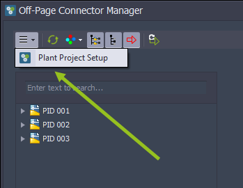
...or PlantProjectManager.

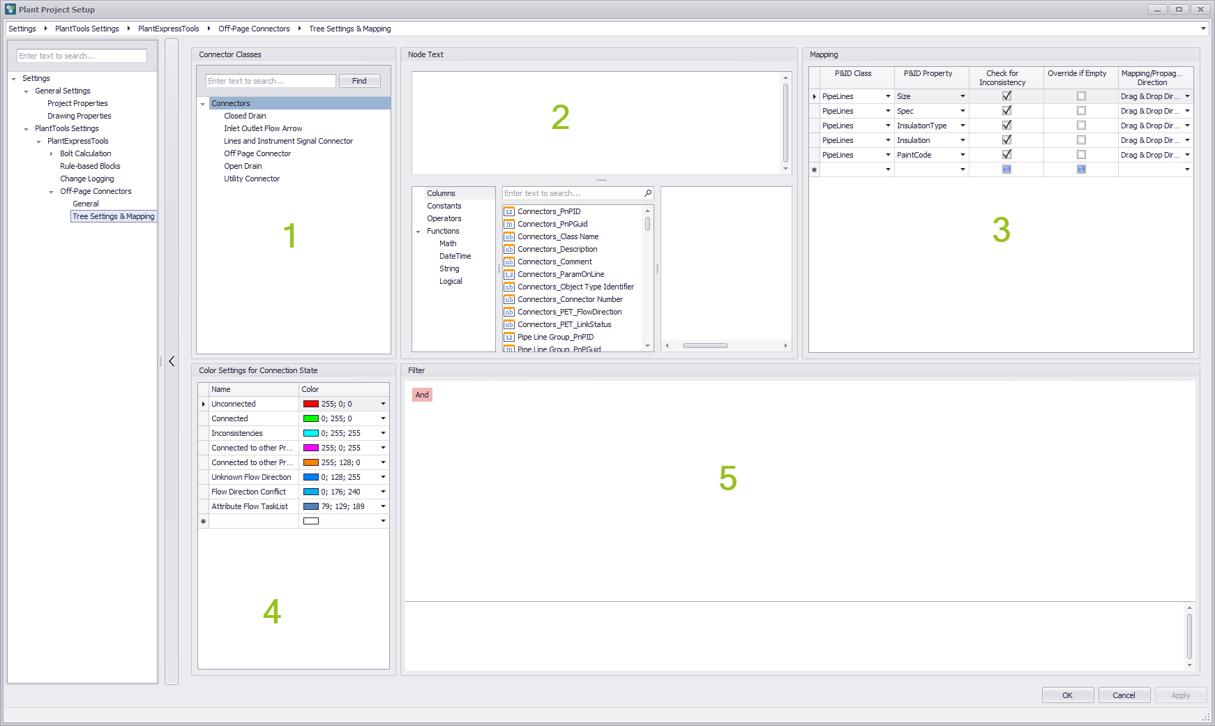
Under Settings\PlantTools Settings\PlantExpressTools\Off-Page Connectors\Tree Settings & Mapping you will see 5 areas which are described in detail blow. If you leave the PlantProjectSetup the OPC Manager (if already open), will be refreshed with the current settings.
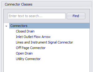
1.Connector classes
This shows all available connector classes which do exist in the current project.
2.Node Text
This allows you to define what text you want to see in the trees of OPC Manager for your OPCs.
3.Mapping
This allows you to define which properties of the Pipe-SignalLineGroup, Pipe-SignalLineGroup, and Connector class you want to map and monitor for inconsistencies.
4.Colors & States
This allows you to change the colors use in the OPC Manager trees to indicate the state of a connection. It also influences the color of the OPC symbols in the drawing.
5.Filtering
This allows you to define a filter expression to be able to hide certain OPC from appearing in the OPC Manager trees at all.
States & Colors
The different connection states are shown with different colors in the OPC Manager trees.
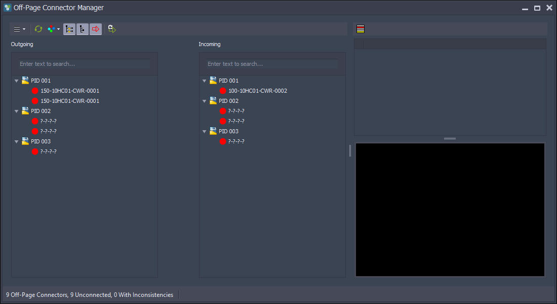
The colors are also used to color the OPC symbols themselves. For this to work the AutoCAD objects in the OPC block must use ByBlock (which is the default setup of PID symbols anyway).
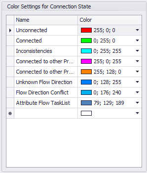
The following shows the list of default States and Colors. You cannot delete any of those States, but you can rename them and change the color.
The States are as follows:
Unconnected |
Shows an OPC which isn't connected |
Connected |
Shows an OPC which is connected and where the properties which are listed under 'Mapping' in the 'Tree Settings' match |
Inconsistencies |
Shows an OPC which is connected, but where one or more properties do not match |
Connected to other Project |
This is currently not supported |
Connected to other Project with Inconsistencies |
This is currently not supported |
Unknown Flow Direction |
Shows an OPC for which we cannot derive the Flow Direction |
Flow Direction Conflict |
Shows an OPC which is connected to another OPC but they show different Flow Directions |
Attribute Flow TaskList |
Shows an OPC where a Task for PlantSpecDriven is pending |
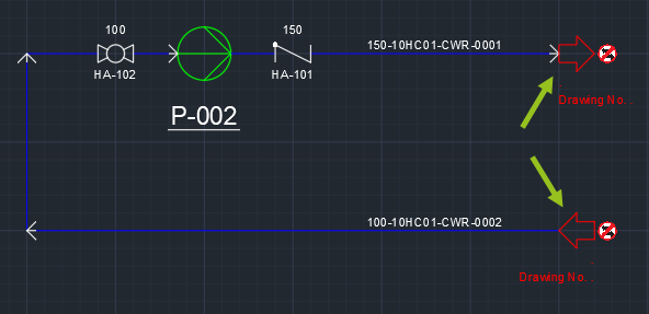
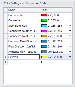
In addition to the existing States you can also create your own States and assign a color. These States can later be used for Unconnected OPCs.
In this example you see a new State which can later be used to 'mark' an unconnected OPC so users in the OPC Manager trees and in the drawing can see, that those OPCs come from the outside of the scope of your P&ID drawings or go to the outside.
Classes
The classes listed here show the existing classes in the current project. If you want to create additional classes for which you want to have different settings you must create them in Project Setup.
Any setting you make to the Node text, Mapping, and Filtering sections are made for the selected class. Settings made for a sub-class (e.g. 'Inlet Outlet Flow Arrow') will supersede the setting of the 'Connectors' class. That means, that you can make some general settings for the 'Connectors' class, and then override it by making a different setting for a sub-class.
Node Text
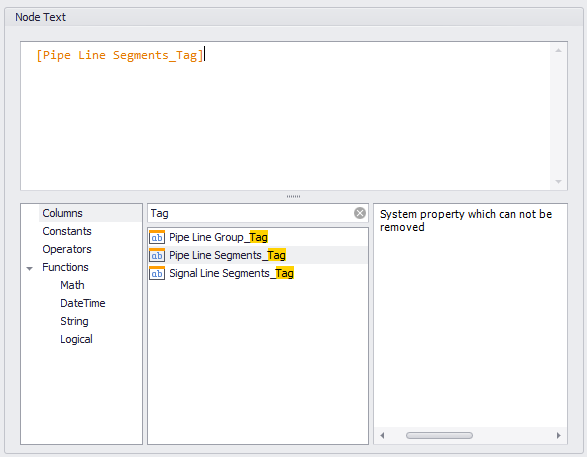
By default the OPC Manager shows the Tag of a line segment as the node text. If you use Signal Line Segments they typically don't have a Tag property. In such cases we show the PnPID if the Signal Line Segment.
To define the node text we use the Expression Editor of DevExpress which is also used for example in PlantReporter, or AutoCAD Plant Report Creator, or PlantExpressTools calculation function, or PlantSpecDriven. So we won't go into detail here.
Under columns you have all properties available of the following classes:
1.PipeLineGroup/SignalLineGroup
2.PipeLineSegment/SignalLineSegment
3.Connectors/Sub-Connector
4.Drawing
5.Project
You can filter the properties as well to find the required property more quickly.
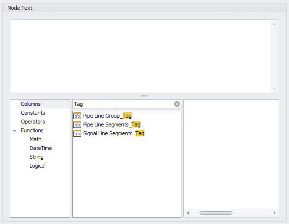
If you double-click on a property it is copied to the expression section at the current cursor position.
You can type in a '+' and then double-click on the 'Connector Number' property.
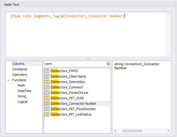
Then we can add some texts as prefixes for the properties.
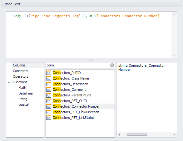
And this is how it looks. Apparently, no connector numbers are given.
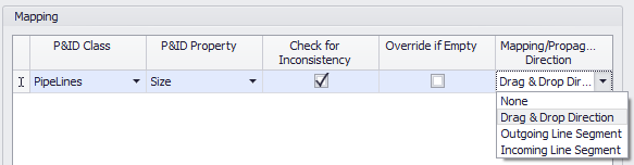
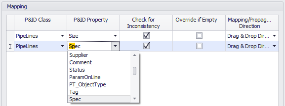
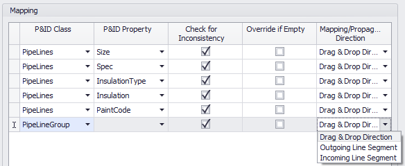
Mapping
Under mapping you can add the properties which should be mapped (and how) when connecting. The option 'Check for Inconsistency' is used to show if there are differences between the values between two OPCs. 'Override if Empty' is used when connecting two OPCs and one OPC has no value. In this case the empty value will be overridden from the other OPC value.
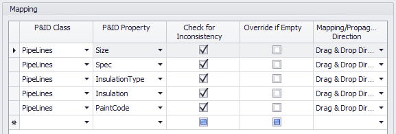
By default the following properties are already mapped.
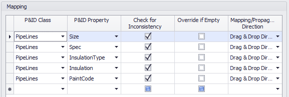
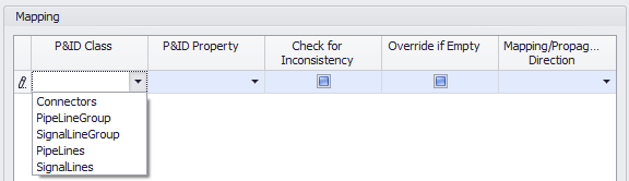
The P&ID Class column shows the available classes. If you selected a connector sub-class (e.g. 'Inlet Outlet Flow Arrow') you will see this class name and not 'Connectors'.
Remark: You may wonder at this point, why you can select the PipeLineGroup and SignalLineGroup class. When you connect two OPCs then the Line Segments which are attached to the two OPCs are merged to the same line group. So there can never be the need to map a property and there can never by an inconsistency for the line group, because it is the same line group for both line segments. However, OPC Manager allows you to connect OPCs, but have the line segments still use their independent line groups.
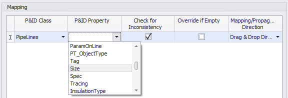
After selecting the class you select the property. Again, all properties are available of the selected class.
The 'Check for Inconsistency' check box makes sure, that if there is a difference between the two property values, it will be shown in the OPC Manager so you can take care of it. Also the node in the tree will change to the 'Inconsistent' state. By default the check box is checked.
The 'Mapping/Propagation Direction' setting allows you to control if and in what direction a difference in value should be copied/propagated. By default the setting is 'Drag & Drop Direction'.
None |
There is no copying of values when connecting |
Drag & Drop |
The dragged OPC/Line Segment is leading and its property values will be copied to the other OPC/Line Segment |
Incoming Line Segment |
This means, that the Incoming OPC/Line Segment is leading. Its values will be copied independent of the drag & drop direction |
Outgoing Line Segment |
This means, that the Outgoing OPC/Line Segment is leading. Its values will be copied independent of the drag & drop direction |
But be careful with 'Incoming/Outgoing Line Segment', because this may be misleading for the user, if the user thinks, that the intuitive drag & drop direction is used.
Since the list of properties can be long, you can also start typing and the properties fill be searched.
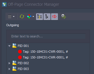
Let's use the following as an example for the documentation.
The setup of mapped properties will be created by default when you activate the OPC Manager the first time for a project.
When using PipeLineGroup/SignalLineGroup you cannot select a property and the 'Mapping/Propagation Direction' cannot be 'None', because when connecting both Line Segments will become part of the same Line Group. You can only influence the direction.
Filtering
Filtering allows you to suppress/hide certain OPCs from the OPC Manager trees.
The editor is also from DevExpress and is used in PlantReporter, or AutoCAD Plant Report Creator, or PlantLink, or PlantSpecDriven. Because of that we won't go into detail here.
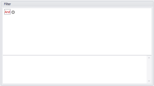
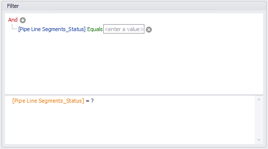
If you click on the '+' a new line appears.
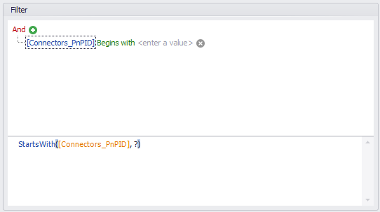
You can click on the property and get a list of all connector and line segment properties.
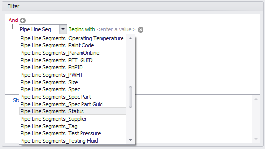
Next you can select the condition.
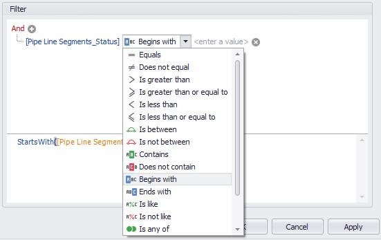
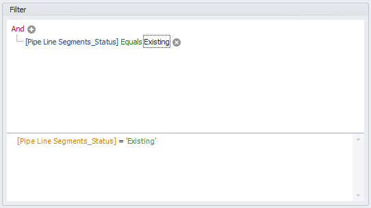
And finally enter a value.
Make sure that you don't use and quotation marks for string values.
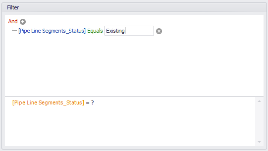
As you can see in the text expression below, the quotation marks will be set automatically.
You can also edit the text expression. This may be useful in case of very complex conditions where the graphical setup gets complicated. If you edit the expression it can lead to the fact, that the graphical secion will be blank, because it cannot be displayed graphically anymore. But this doesn't mean that the condition is wrong.
Next Chapter: Usage