|
<< Click to Display Table of Contents >> Page 14 - AutoPipe - Fasteners |
  
|
|
<< Click to Display Table of Contents >> Page 14 - AutoPipe - Fasteners |
|
If you disabled AutoPipe on the previous page you cannot define any settings on this page either.
if you don't need Fasteners like Gaskets in your P&IDs, then you can just skip over this page.
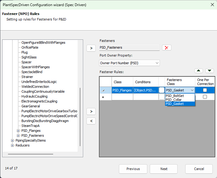
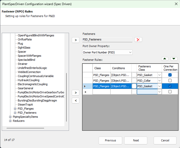
The first thing you do is selecting the Fasteners class in the tree and then click on the top right arrow to copy the class name to the right.
Next you select the property which stores the Port/AttachmentPoint number in the Fastners object so PlantSpecDriven know to which Port/AttachmentPoint a Fastener belongs to.
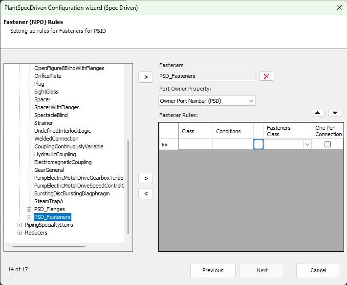
In the grid you then define the condition when to insert Fasteners. When you click into the Condition Cell you will see a button with "...". Click on that button to open the dialogbox where you can type in the condition. The condition can be become very complex. Further down we show some common examples.
If you need multiple Fasteners for a class with a specific condition you just create a new line for the same class with the same condition as before.
The order in the grid is important. Therefor you can move rows in the grid up and down with the two arrows on the upper right hand corner of the grid.
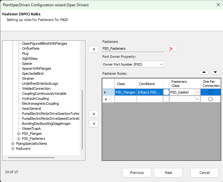
In the last column you use the checkbox if this Fastener should be inserted just once between two P&ID Symbols. For example, if two lapped flanges are used you want just one Gasket, but both flanges need a Collar/StubEnd. For flanges you check the Gasket, but not for the Collar.
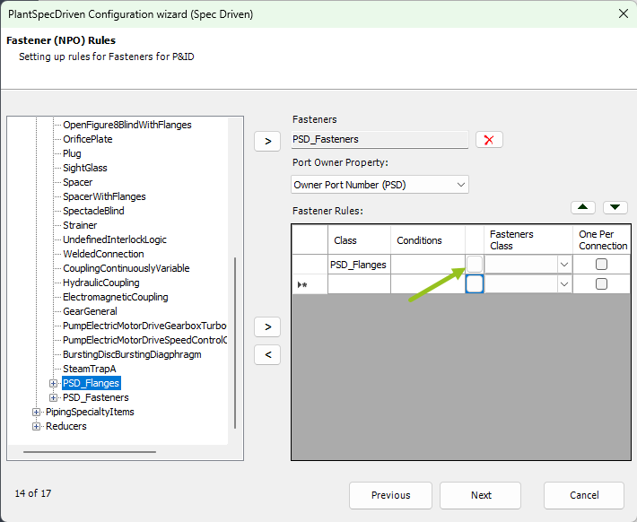
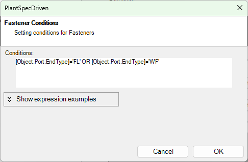
To add a row to the list you first select the class the Fasteners should be assigned to. Again my selecting the class in the tree and then use the bottom right arrow to copy the class name. Then you click on the button behind the Condition column.
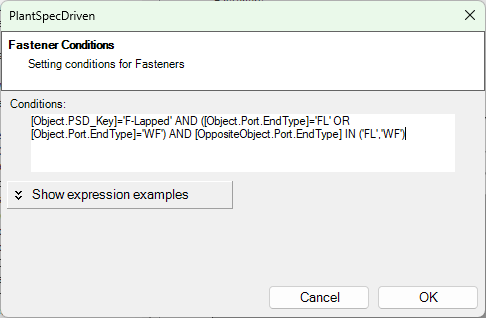
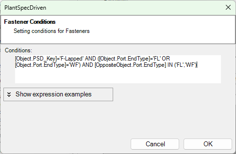
Here we have the following example from Test Projects.
[Object.PSD_Key]='F-Lapped' AND ([Object.Port.EndType]='FL' OR [Object.Port.EndType]='WF') AND [OppositeObject.Port.EndType] IN ('FL','WF')
What is does is, add a Fastener if the PSD_Key value of the flange (Object. is the inserted flange or valve) equals F-Lapped (see PSD_Key Suggestion) and the flange has an EndType of FL or WF and The opposite object (e.g. a valve) also has FL or WF.
As you can imagine the expressions can be very tricky.
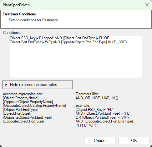
If you click on Show expression examples you can see which options you have.
After selecting the condition you select which Fastener you want to get.
Finally, if you want only 1 or 2 of the selected Fasteners. If you think about a flange/flange or flange/valve connection you only need 1 Gasket. In this case you select One Per Connection.
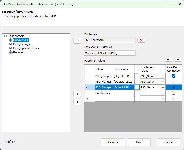
Then we add another row again for flanges.

We use the same condition as before.
Now we select the Collar/StubEnd class. But now you do not check the One Per Connection box, because you need to StubEnds.

For the third row we have a slightly different condition. The difference is that we use F-WeldingNeck instead of F-Lapped.
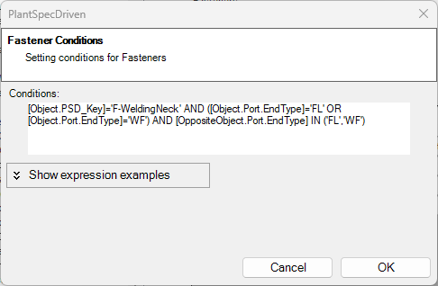
Again only 1 Gasket per connection.
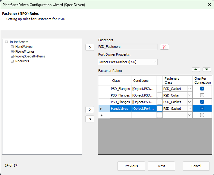
Finally we select the Hand Valves class in case you put two valve symbols side by side in your P&ID. In this case there won't be a flange in between the valves, but you need a gasket.
This time the condition looks very simple. It just checks if the EndType of the valve is either FL or WF.
And again one per connection.
Next Chapter: Page 15 - P&ID <--> 3D Mapping