|
<< Click to Display Table of Contents >> Create Equipment List |
  
|
|
<< Click to Display Table of Contents >> Create Equipment List |
|
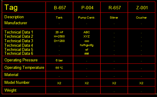
In this first example we want to create the setup for the equipment list, because this one of the most common use cases.
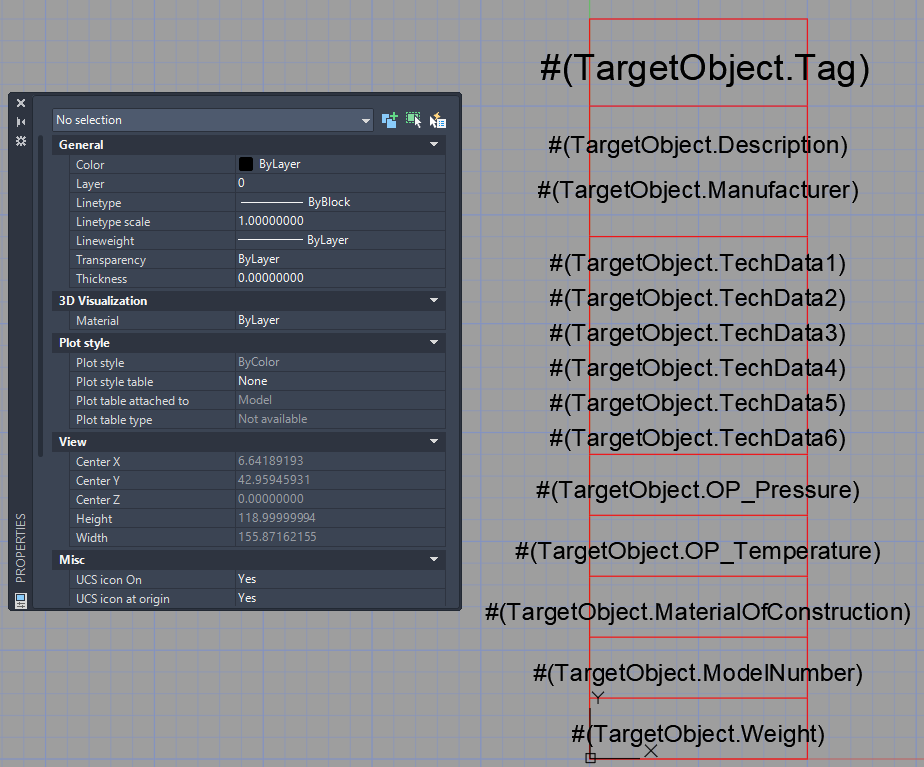
The first column of the list is the title block or header of the list. The next four columns are actually annotations for the four pieces of equipment in that drawing.
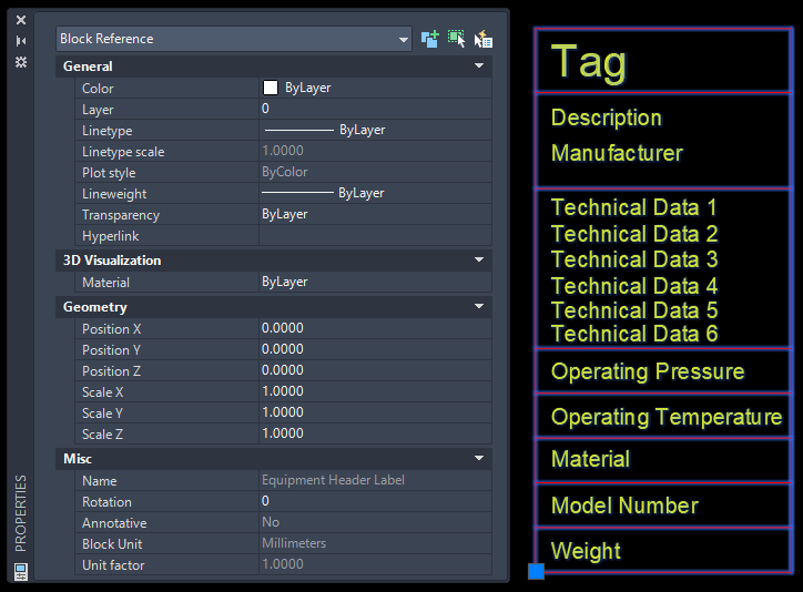
For this example we create a standard AutoCAD DWG with a block which looks like this. This is just a simple block with lines and texts. The insertion point should be in the lower left hand corner. But the insertion point is not that important. It makes sense to have it in one of the corners, because later we must define where the list should start and the title block is the first thing to be inserted.
The drawing with the block can be located anywhere. It makes sense to place the DWG somewhere in the project. The list function will later create the folder "ListConfigurations" where the setups will be located.
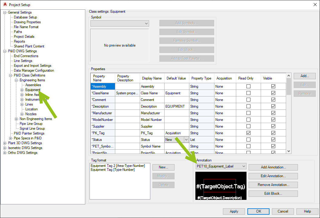
As mentioned above, the parts of the list which show the actual data are standard Plant 3D annotations. The annotation must be available for the classes which should be included in the list.
This is how the annotation block in this example looks like.
Now that we have done all the leg work we can finally start with the configuration of the equipment list.
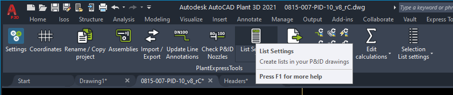
We click on the List Settings button in the ribbon.
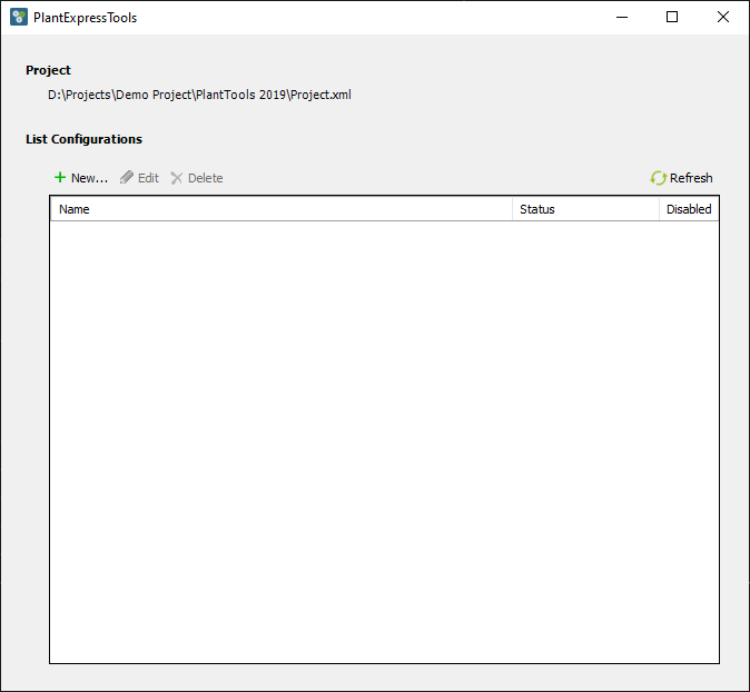
We get a blank dialog and click on "New...".
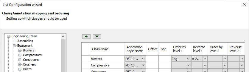
The first thing we do is selecting the class or classes we want to have in the equipment list. Theoretical we could just select the Equipment class. However, most customers do not want to have electrical motors or gears in the equipment list. The are under "Mechanical Drivers".
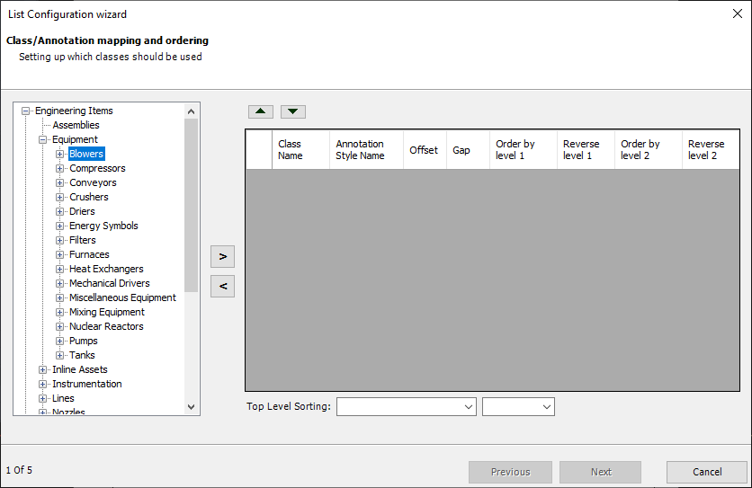
Therefore, we add each equipment class separately by selecting a class and clicking on the arrow right button.
If you selected a class which you want to remove you select the class and click on the arrow left button or the DEL key.
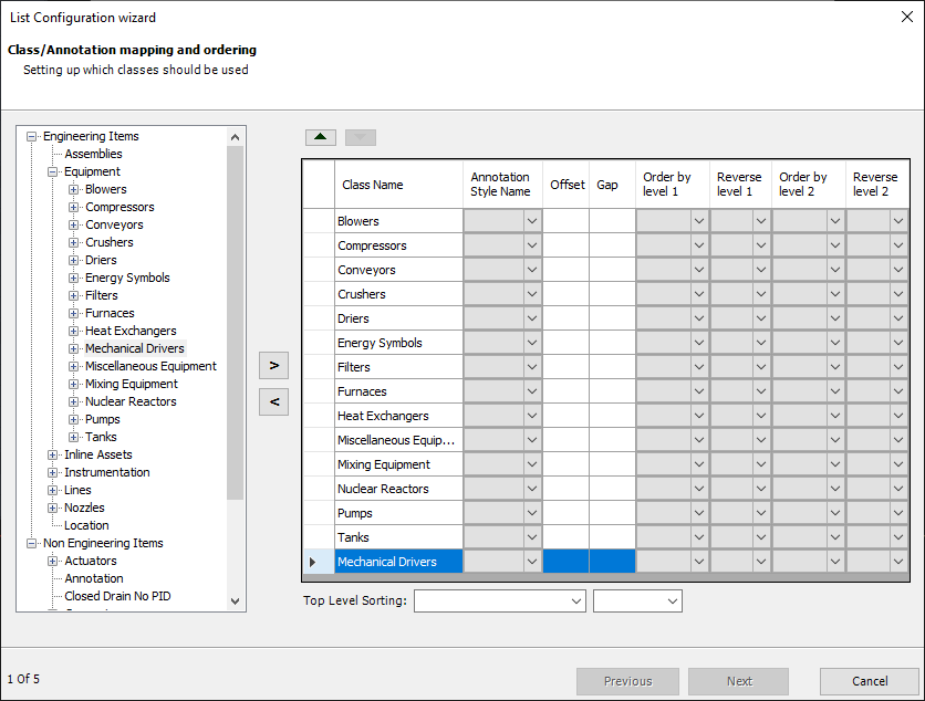
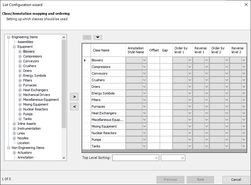
No we have all the classes we need.
For the first class we select the new annotation we created.
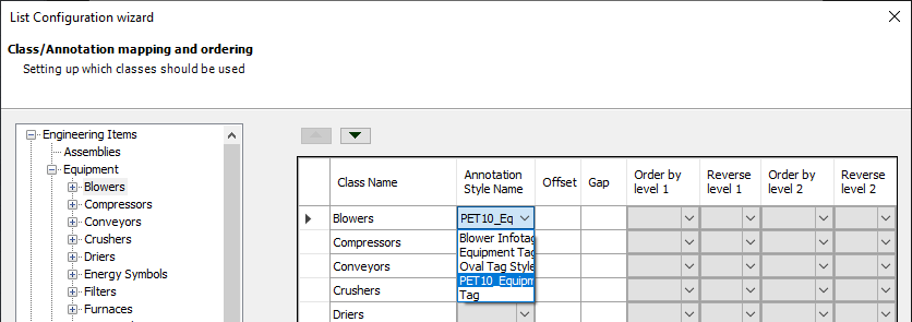
We repeat this for all classes. To speed this up you can click in the dropdown list and press p, since this is the only annotation starting with a p.
Under "Order by level 1" you select the property by which you want to order.
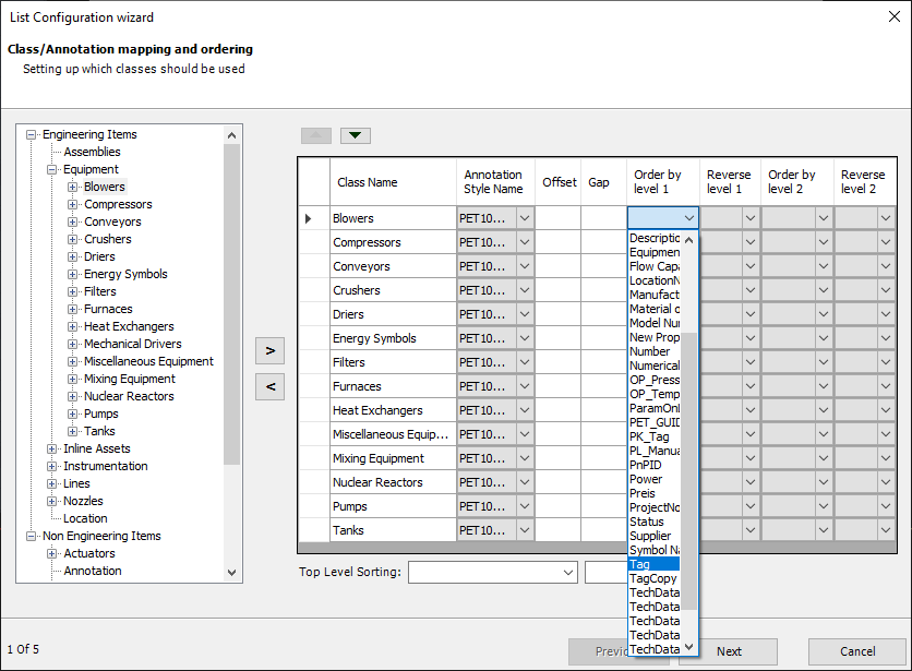
Under "Reverse level 1" you select A-Z, because the Blowers are supposed to be ordered by Tag in ascending order.
You set Tag and the order for all classes.
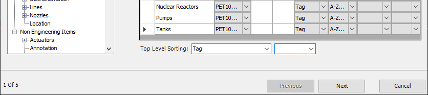
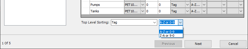
Since we use multiple classes, we probably want to order the equipment symbols without considering the classes. Meaning all equipment symbols should be ordered by Tag throughout class names.
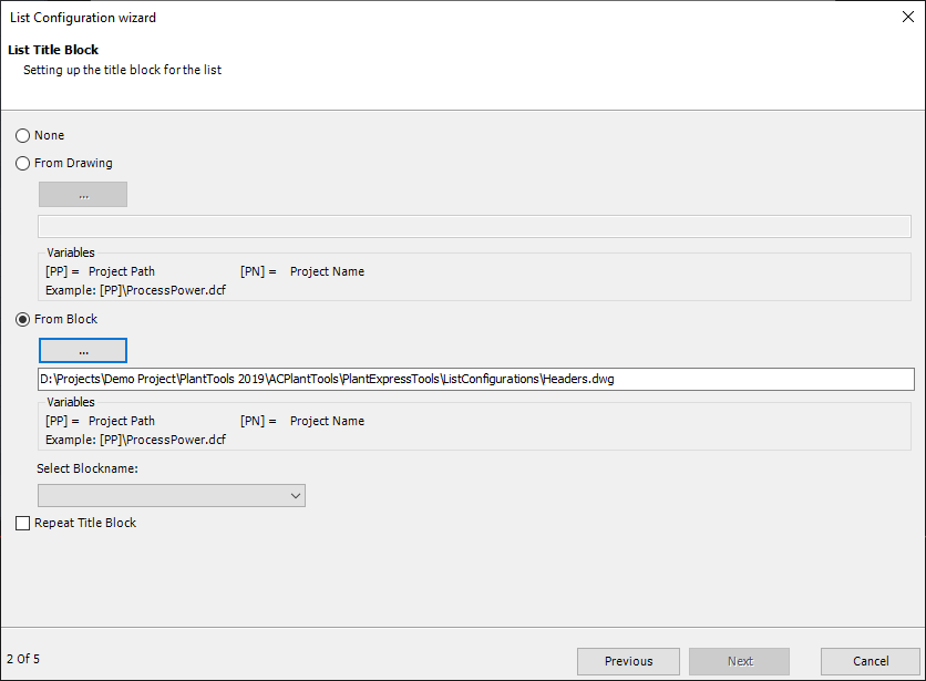
Next is the title block. if you don't need a title block you select "None".
If you need a title block you have two choices. "From Drawing" is used when the drawing you are about to select is the block. In this case the selected drawing will later be inserted as a block.
The option we will use in this example is "From Block". In this case there is a block within a drawing. And this is what we setup at the top.
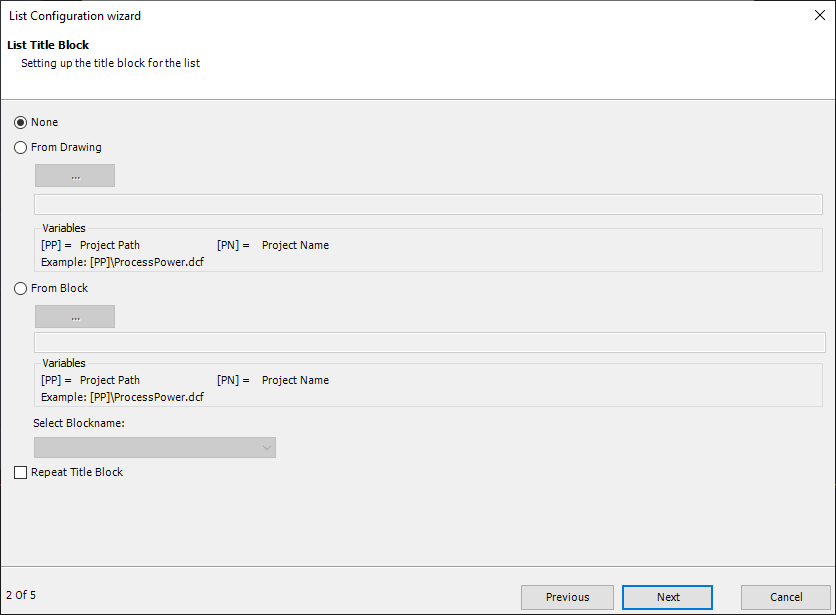
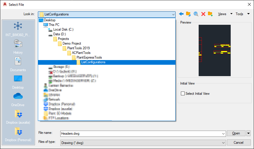
Select "From Block" and then select the DWG we created earlier.
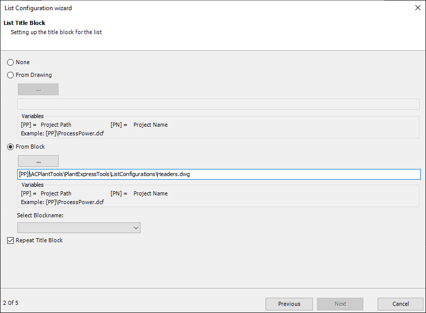
As you can see in the dialog, you can also use variables. This is useful in case the project will later be copied or moved. We essentially create relative paths.
We replace "D:\Projects\Demo Project\PlantTools 2019" with "[PP]".
Last you can check the "Repeat Title Block" box to get a title block for each row in the equipment list in cases where the list will be so long, that one row isn't enough.
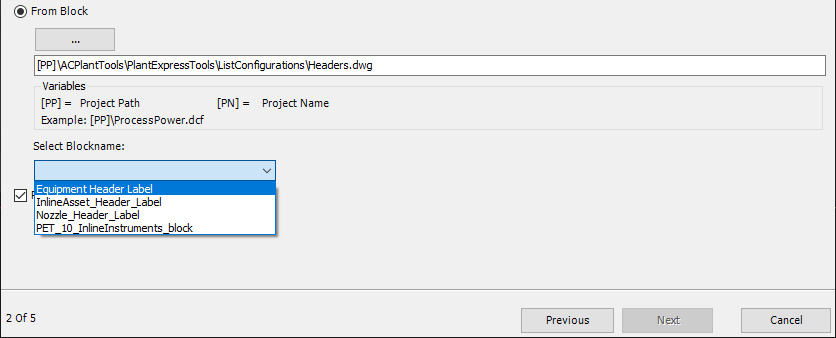
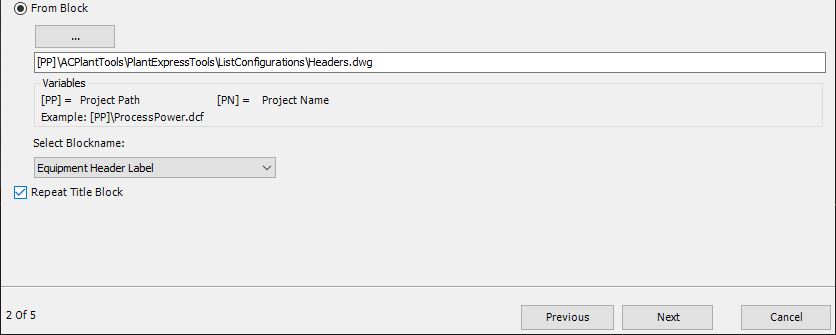
Finally we must select the block in our DWG which then will be inserted as the title block.
This is how it looks like now.
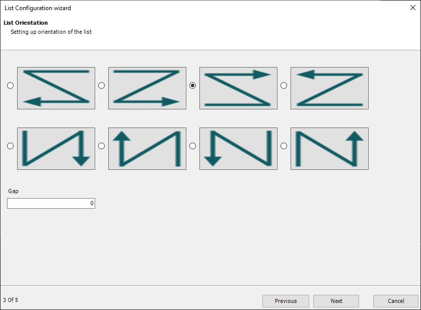
Next we select the orientation. In our case the equipment list starts in the lower left hand corner and first goes to the right, before continuing above again from left to right.
The "Gap" option in for cases where you want to have a gap between the rows or columns (depending on the orientation).
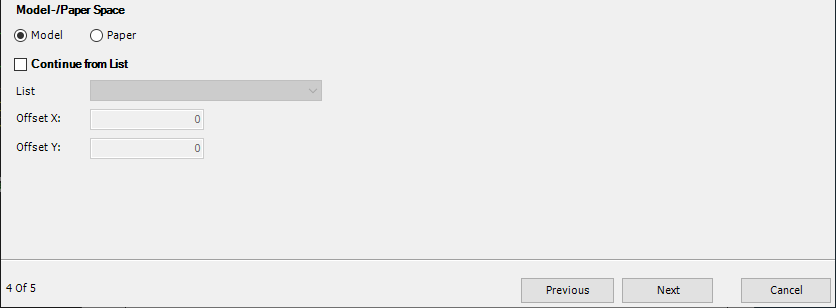
Next we need to define where the equipment list is supposed to start, which space it can use and whether it should be in Model or Paper Space.
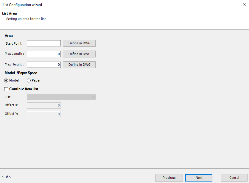
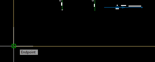
Lets start with the Start Point. If you know the coordinates you can type them in. Or you click on "Define in DWG".
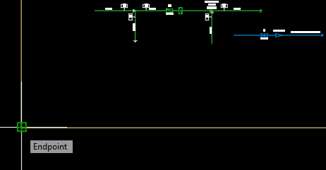
You then select the start point.
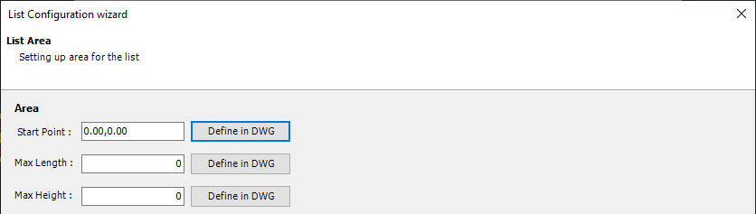
You will see the coordinates in the dialog.
Then you click on "Define in DWG" for Max Length.
Start at the left...
... and then pull to the right. If you want you can create a square. However, only the Length in X is used.
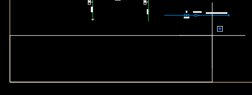
This is what the result is.
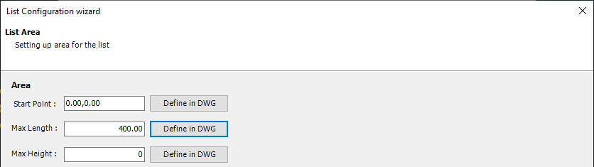
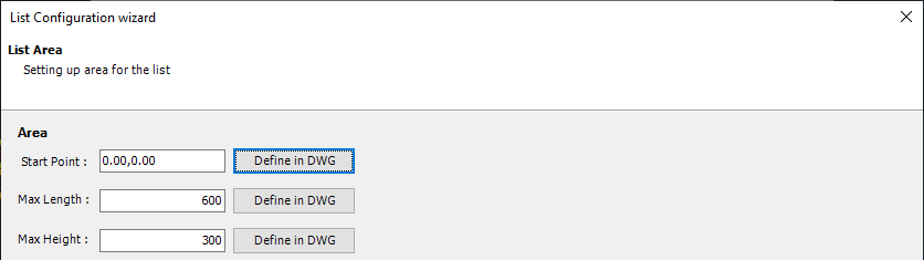
You can simply override the value or type them in.
Below you select either Model or Paper Space. In our example Model.
The option to "Continue from List" will be covered under Create Following Lists.
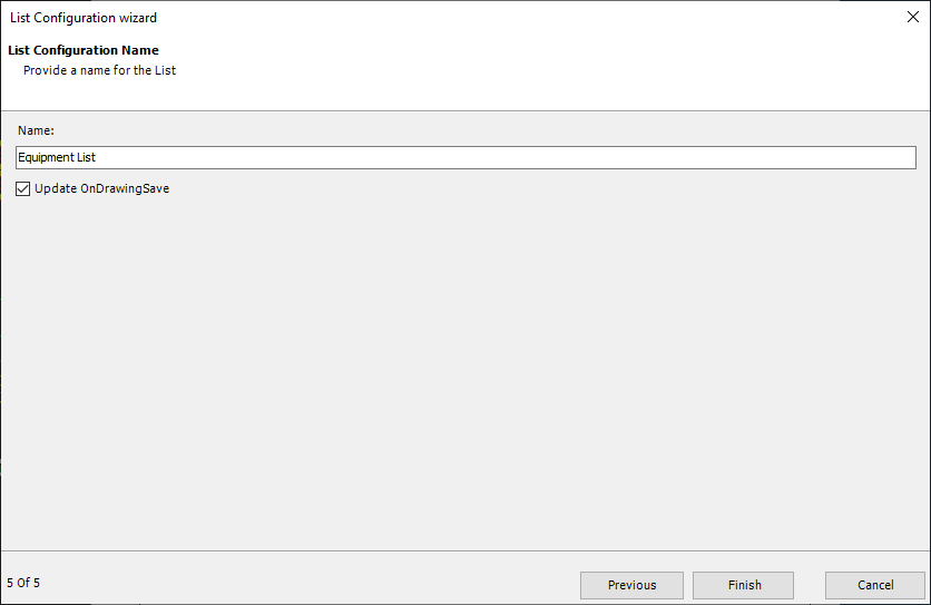
Finally, you enter a name for the list.
You can also check the box for "Update OnDrawingSave". if this box is checked the list will be updated when you save the drawing. But the checkbox in the settings under "OnDrawingSave" must be checked as well.
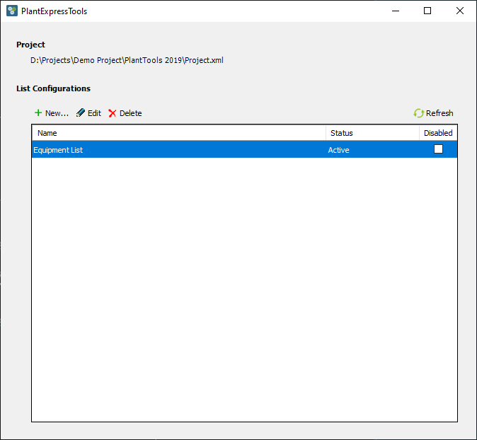
After you click on Finish you see the list marked as Active. If there is some issue with the configuration you will see an error under Status.
If needed you can deactivate a list configuration in cases where you want to test or simple because a list isn't required in each drawing.
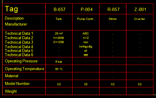
The result looks as expected.
Next Chapter: Create Following Lists