|
<< Click to Display Table of Contents >> 3D Settings |
  
|
|
<< Click to Display Table of Contents >> 3D Settings |
|
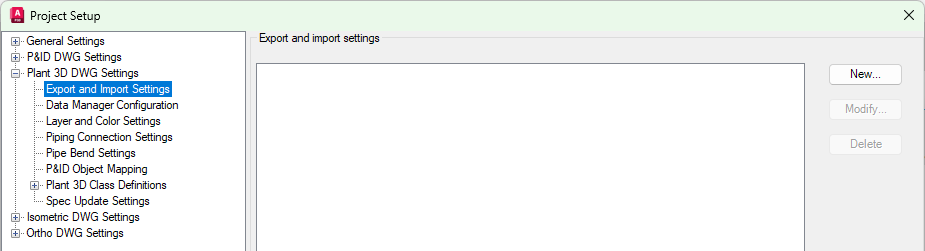
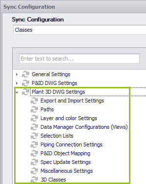
This chapter describes the options for the 3D DWG Settings.
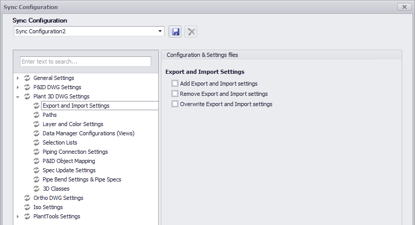
These settings can be found under Export and Import Display Settings.
Enabling Add Export and Import settings will copy the export/import settings to the target projects if they don't exist in the target project. Enabling Remove Export and Import settings will remove the export/import settings in the target projects if they don't exist in the source project. Enabling Overwrite Export and Import settings will overwrite the export/import settings in the target projects with the configuration of the source project.
|
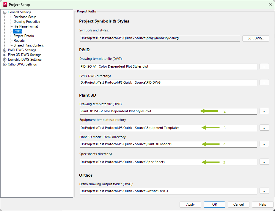
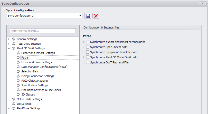
These settings can be found under Paths and Project Details.
The numbers on the arrows above correspond with the numbers below. The path for the export and import settings (located under the ImportExportSettings folder) cannot be adapted through some user interface. The path is set in xxx_PipingPart.xml and can adapted only manually.
|
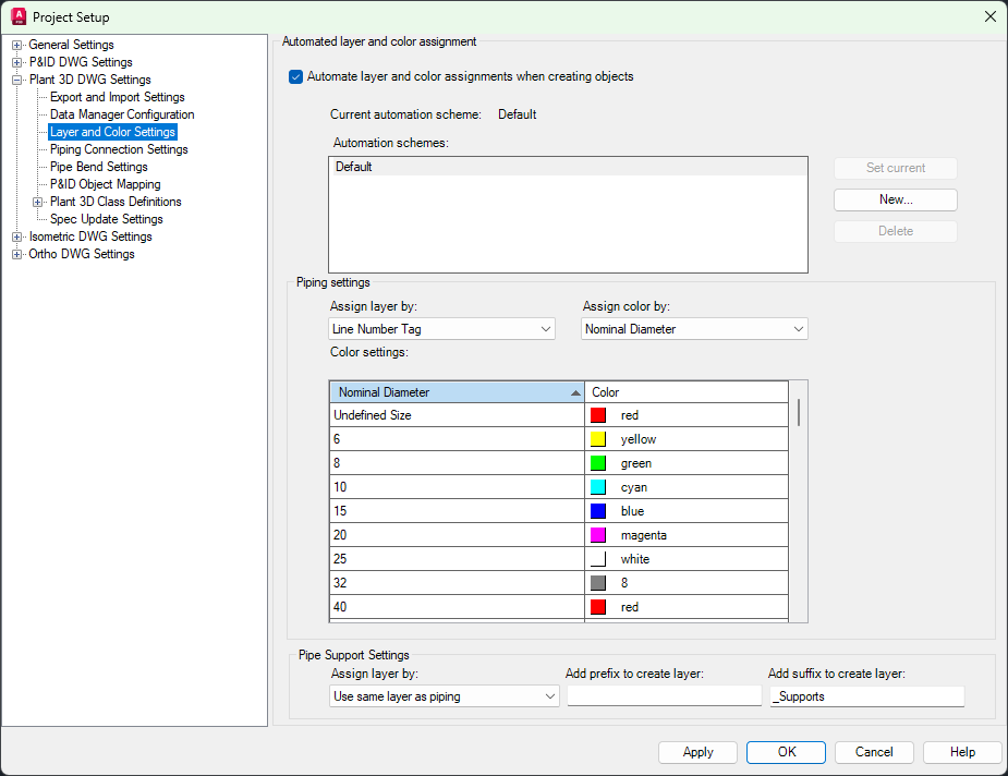
These settings can be found under Layer and Color Settings.
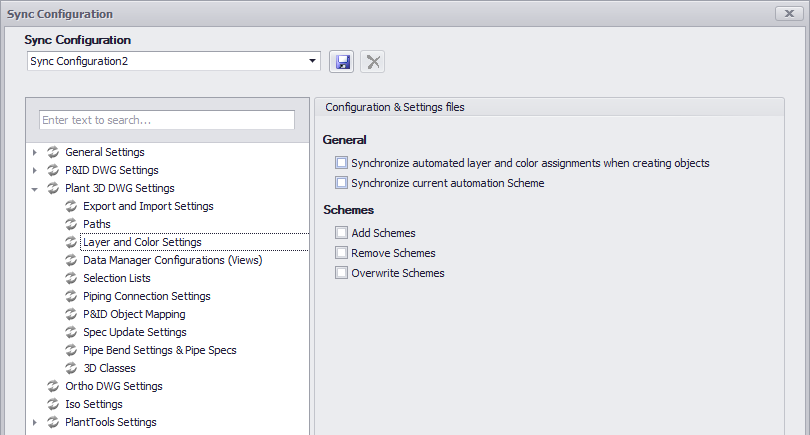
Enabling Synchronize automated layer and color assignments when creating objects will copy the setting of the option to the target project. Enabling Synchronize current automated Scheme will copy the selected Scheme to the target project.
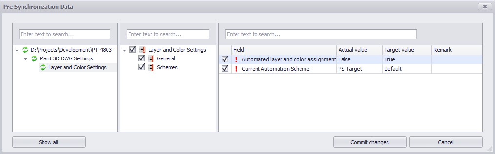
This is how it looks like if there are differences. When selecting General in the middle column you can see the changes for the two settings.
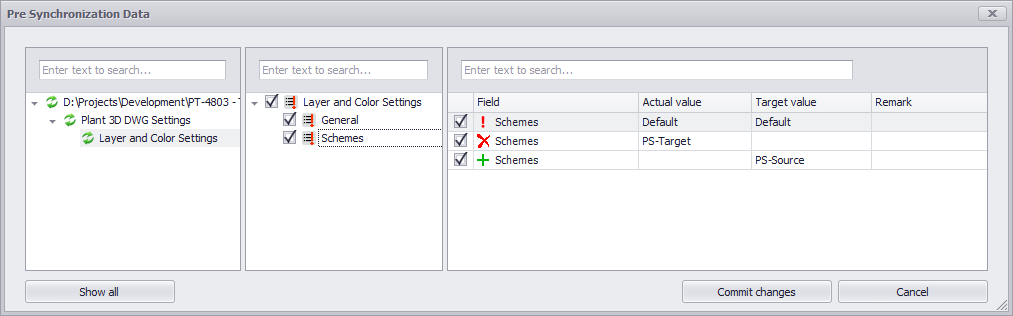
Enabling Add Schemes will copy the Schemes to the target projects if they don't exist in the target project. Enabling Remove Schemes will remove the Schemes in the target projects if they don't exist in the source project. Enabling Overwrite Schemes will overwrite the Schemes in the target projects with the configuration of the source project.
|
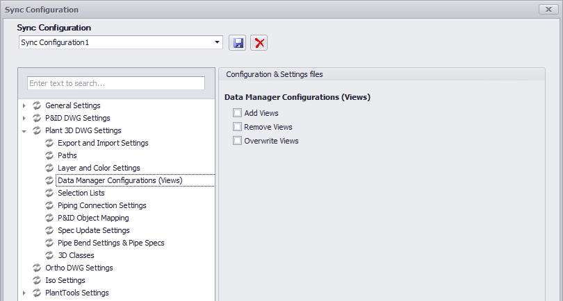
![]() Data Manager Configuration (Views)
Data Manager Configuration (Views)
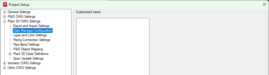
These settings can be found under Data Manager Configuration.
Enabling Add Views will add the Views to the target projects if they don't exist in the target project. Enabling Remove Views will remove the Views in the target projects if they don't exist in the source project. Enabling Overwrite Views will overwrite the Views in the target projects with the configuration of the source project.
|
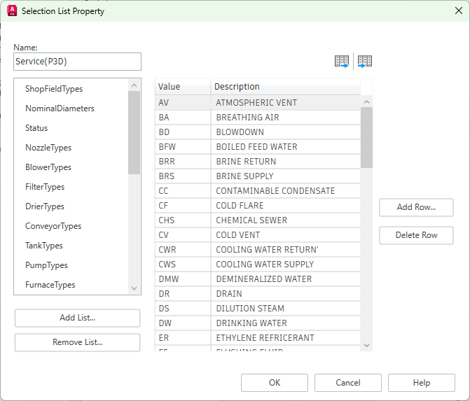
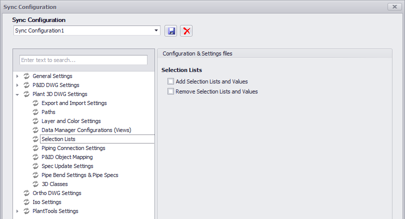
The Selection Lists can be fund when clicking on the Edit button of a property which uses a Selection List. For example, Service for Pipe Line Groups.
Enabling Add Selection Lists and Values will add the Selection Lists and their Values to the target projects if they don't exist in the target project. Enabling Remove Selection Lists and Values will remove the Selection Lists and their Values in the target projects if they don't exist in the source project. The overwrite option is missing which will be added in a future version. However, overwrite will be handled anyway.
|
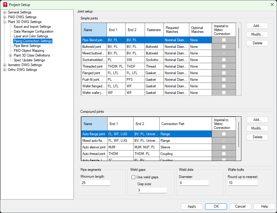
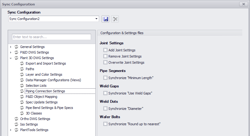
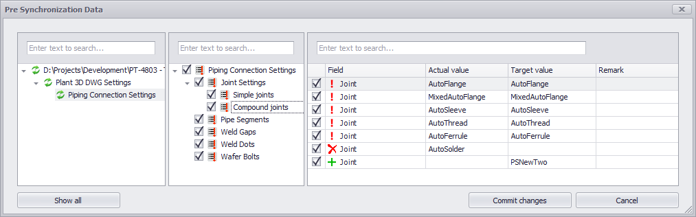
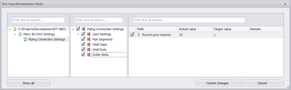
These settings can be found under Piping Connection Settings.
Enabling Add Joint Settings will add the Joint Settings to the target projects if they don't exist in the target project. Enabling Remove Joint Settings will remove the Joint Settings in the target projects if they don't exist in the source project. Enabling Overwrite Joint Settings will overwrite the Joint Settings in the target projects with the configuration of the source project.
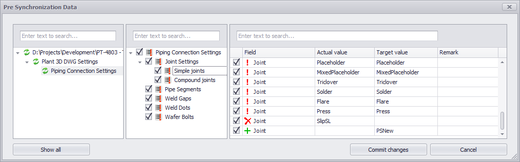
This is how it looks like if there are differences. In the middle column you can see Simple joints and Compound joints. In the right table you can see which Joints will be overwritten, or will be removed, or will be added.
The same applies to the Compound joints.
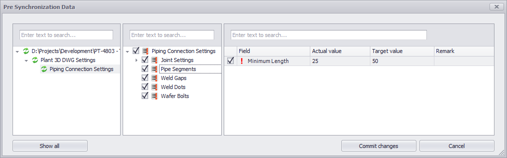
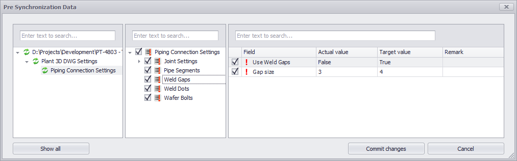
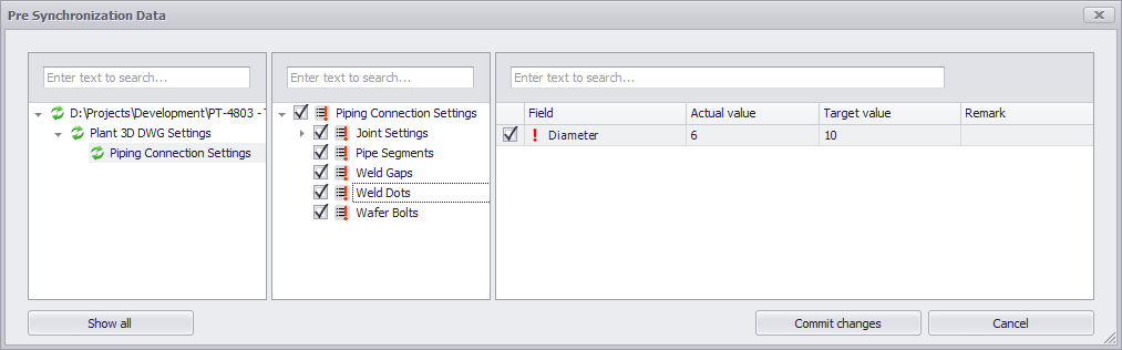
If there are difference in the additional Joint Settings you will see them in individual nodes in the tree in the middle.
|
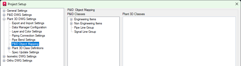
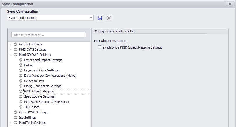
These settings can be found under P&ID Object Mapping.
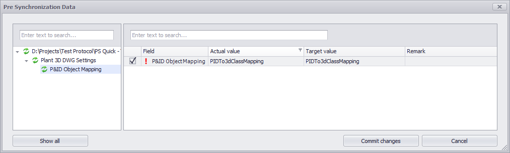
Enabling Synchronize P&ID Object Mapping Settings will copy the options to the target projects. The settings are stored in the project's PIDTo3dClassMapping.xml file.
This is how it looks like if there are differences.
|
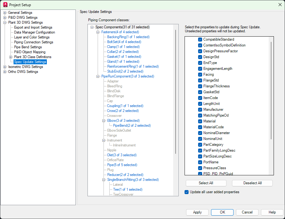
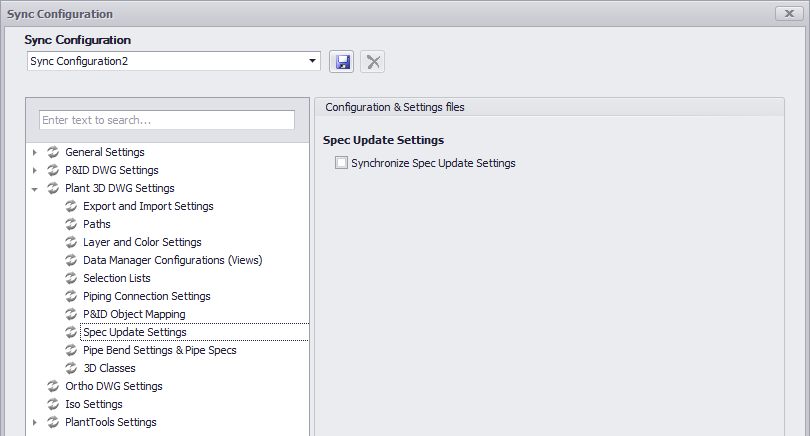
These settings can be found under Spec Update Settings.
Enabling Synchronize Spec Update Settings will copy the options to the target projects. The settings are stored in the project's PIDToSpecClassMapping.xml file.
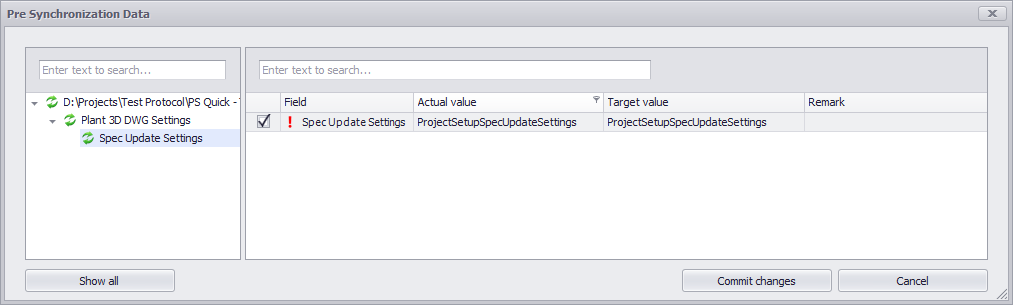
This is how it looks like if there are differences.
|
![]() Pipe Bend Settings & Pipe Specs
Pipe Bend Settings & Pipe Specs
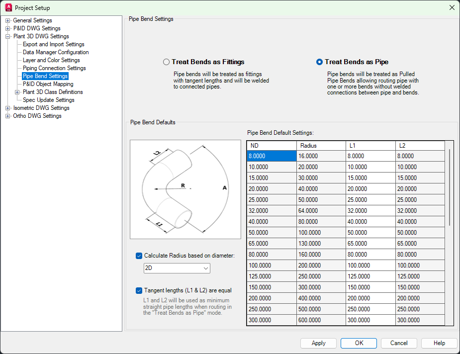
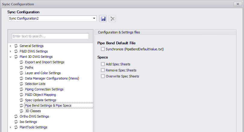
These settings can be found under Pipe Bend Settings.
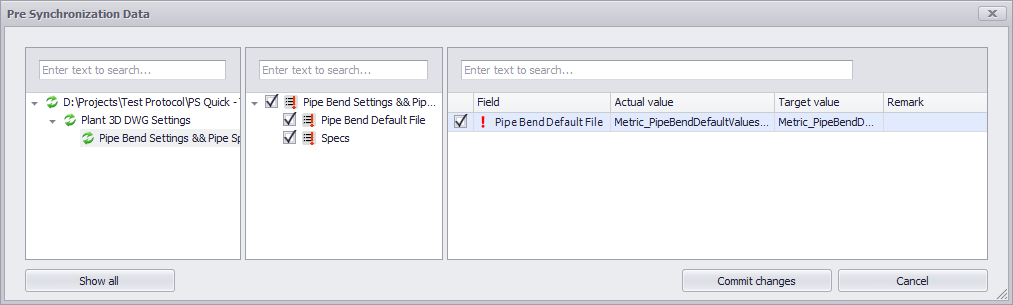
This is how it looks like if there are differences in PipeBendDefaultValue.txt.
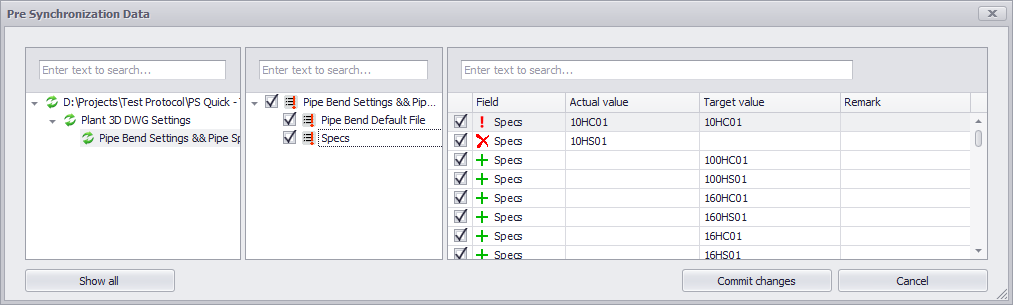
This is how it looks like if there are differences with the Pipe Specs. When selecting Specs in the middle column you you can see in the right table which Pipe Specs will be overwritten, or will be removed, or will be added.
|
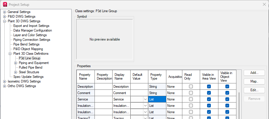
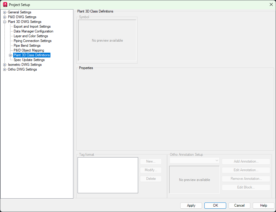
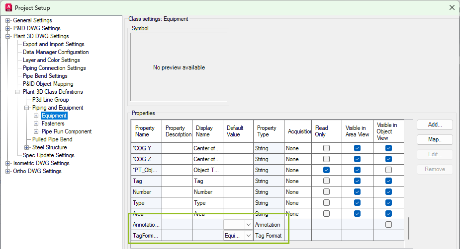
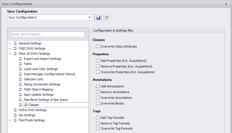
These settings can be found under Plant 3D Class Definitions.
Enabling Overwrite Class Attributes will overwrite the Class Attributes in the target projects with the configuration of the source project. Class Attributes can be found in the list of Properties of a Class. Where Properties contain the data of a drawing object, the Attributes contain system-related settings like the assigned Tag Format Name or the Annotation Style Name. Remark: in 3D Classes cannot be added or removed. Therefore, these options are missing.
The behavior for Properties, Annotations, and Tag Formats is the same as in P&ID (P&ID Settings).
|
Next Chapter: Ortho Settings