|
<< Click to Display Table of Contents >> Understanding Fasteners (P&ID) |
  
|
|
<< Click to Display Table of Contents >> Understanding Fasteners (P&ID) |
|
This chapter describes how PlantSpecDriven adds Fasteners like Gaskets or StubEnds after the End Connection symbols have been inserted.
To get Fasteners at all you firstly have to use End Connections as describes in the previous chapter (Understanding AutoPipe (P&ID)). The setup for Fasteners can be found under Page 14 - AutoPipe - Fasteners in The Wizard of PlantSpecDriven.
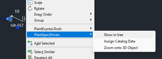
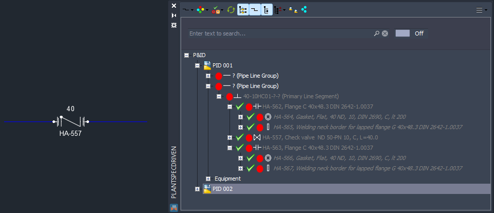
We use a check valve in size 50. Since the Fasteners are created as so called Not-Placed Objects in the P&ID database, they cannot be selected in the drawing. You have to use the Structure Tree which will be explained in more detail in the next chapter.
To get to the Structure Tree you select the flange and use Show in tree from the PlantSpecDriven menu.
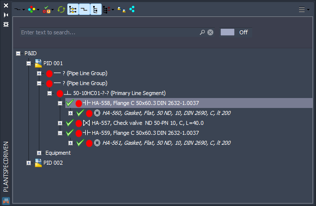
If the PlantSpecDriven Structure Tree isn't already open it will be opened now. The flange is selected. Under the flange we see the Gasket.
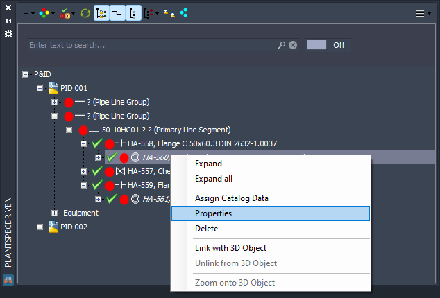
If you make a right click on the Gasket and select Properties a properties dialog opens.
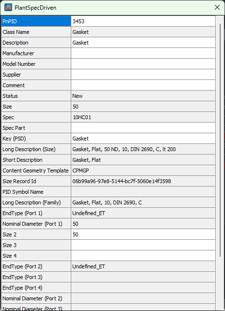
Here you see all data assigned from the pipe spec.
Currently the PlantSpecDriven Properties Dialog isn't using the PlantExpressTools Properties Palette.
If you change the size to 40, then we get lapped flanges. And in addition to gaskets we also get the welding neck borders (or StubEnds) under the lapped flanges.
The line segment and the nodes below are greyed out, because the tree is setup in a way, that everything below size 50/2" will be hidden. See Tree Settings.
Next Chapter: Understanding the Structure Tree (P&ID)