|
<< Click to Display Table of Contents >> Understanding the Structure Tree (P&ID/3D) |
  
|
|
<< Click to Display Table of Contents >> Understanding the Structure Tree (P&ID/3D) |
  
|
This chapter describes additional views on the Structure Tree as an extension of the chapter Understanding the Structure Tree (P&ID).
Now that we have also a 3D drawing we can have a look at the different views of the Structure Tree.
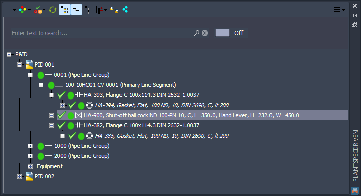
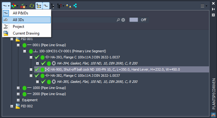
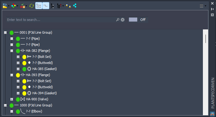
Besides the default view of the P&ID data, you can also get a tree on the 3D data.
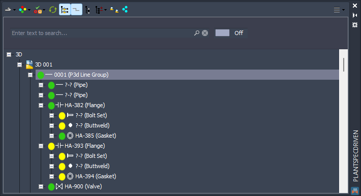
Now you see also the Line Group (but now it is the P3d Line Group and not the Pipe Line Group from P&ID). You see Bolt Sets, Buttwelds, Pipes and so on. What yopu don't see are Pipe Line Segments, because as mentioned before, there are no line segments in 3D. The tree can be configured for example to suppress the Buttwelds or Pipes and so on. You can also change the node text as it is done for P&ID in Test Projects. See Tree Settings.
You can also switch to Current Drawing which then updates the tree as soon as you switch to another drawing.
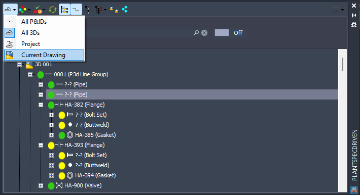
You will only see the data of the current drawing. Therefore the drawing node (e.g., 3D 001) is gone. Other that that, everything else is the same.
When you switch to a P&ID drawing you see only what's in this drawing with no Drawing node.
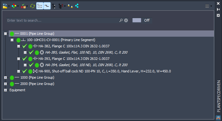
Finally, there is the Project view which combined the P&ID and 3D data of the project.
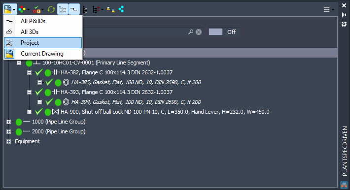
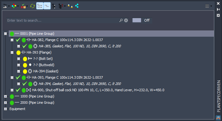
This almost looks like the 3D tree, but the node texts come from P&ID, because the P&ID is leading in case objects are linked.
Next Chapter: Linking Equipment and Nozzles (3D)