|
<< Click to Display Table of Contents >> Linking Equipment and Nozzles (3D)) |
  
|
|
<< Click to Display Table of Contents >> Linking Equipment and Nozzles (3D)) |
|
This chapter describes how you manually link P&ID and 3D Equipment.
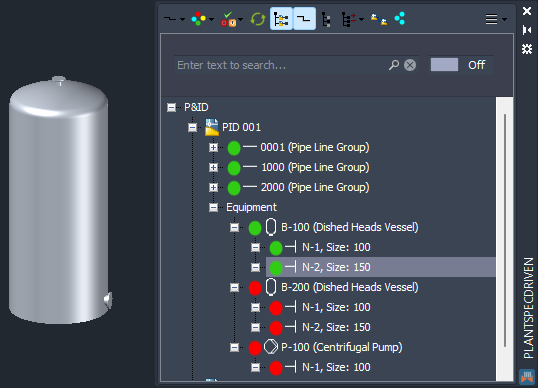
To link a P&ID Equipment or Nozzle to the 3D counterpart you have to have the 3D drawing open where the Equipment or Nozzle originate. Therefore not in a 3D drawing the Equipment is xreffed into.
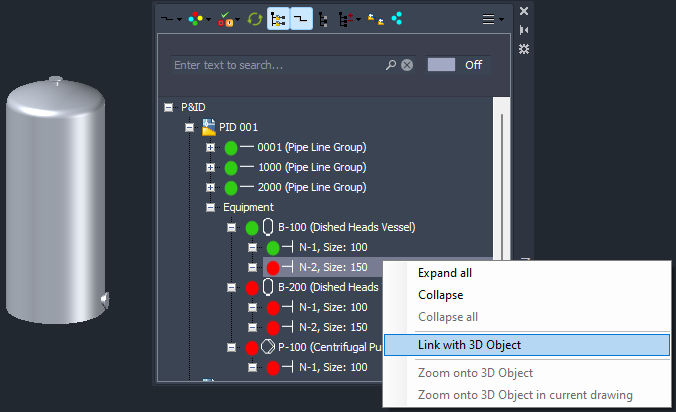
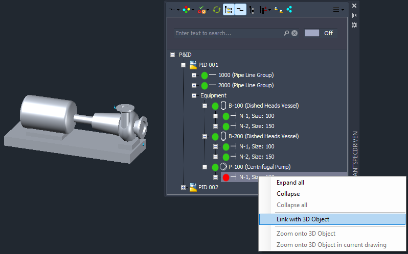
You then use Link with 3D Object.
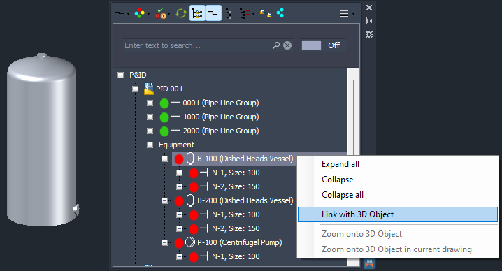
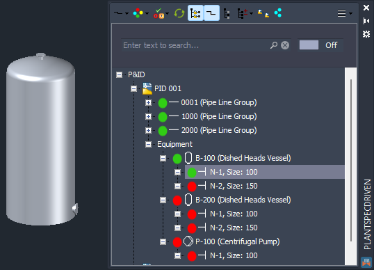
The you select the equipment until it is highlighted.
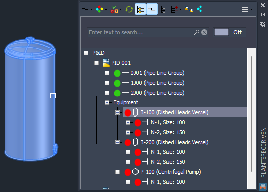
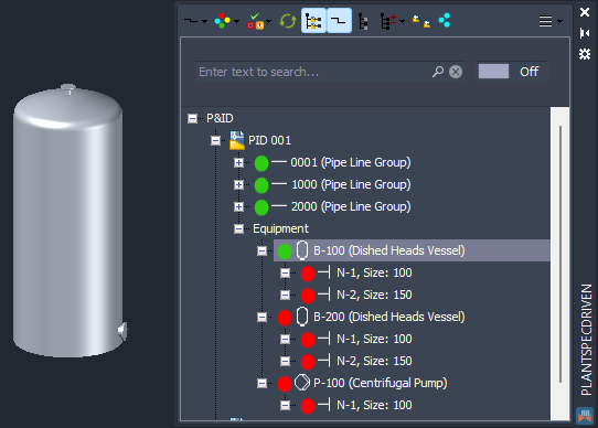
Now the 3D Equipment is linked to the P&ID Equipment.
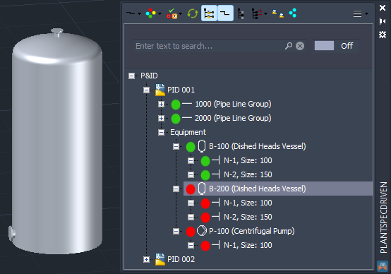
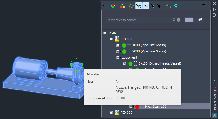
Nozzles work the same way. You use Link with 3D Object again.
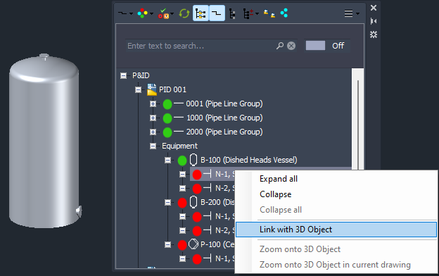
You select the nozzle. You don't necessarily need to wait till the tooltip of the nozzle appears, but it is a way to see the Tag of the 3D Nozzle to know that you are on the right Nozzle.
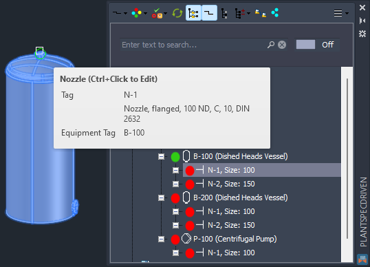
After selecting the Nozzle the Nozzle is linked.
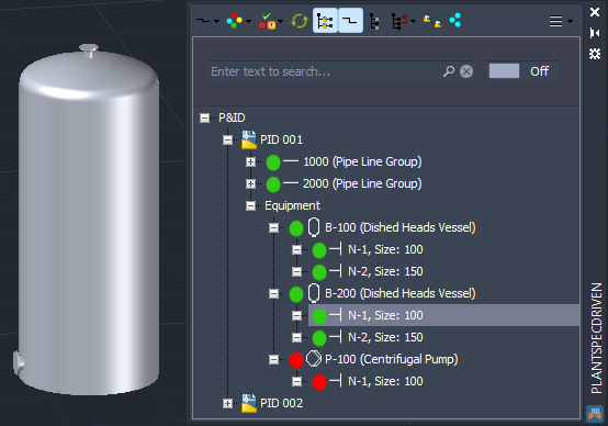
And then the next one.
Looks correct.
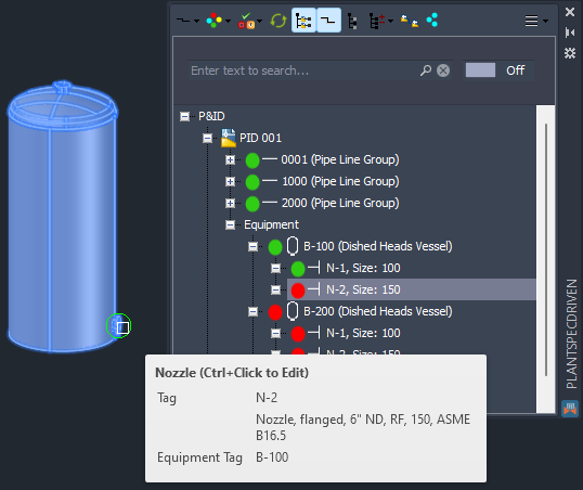
And now both nozzles are linked.
We repeat this process for the second tank and nozzles.
Everything is linked again.
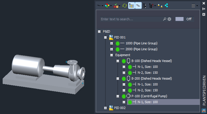
Before we link the pump, recognize, that the pumps seems to have just one nozzle. Remember that this is the P&ID view of the data and the Pump Symbol in this example has no line segment connected to the suction side of the pump.
We continue linking the pump.
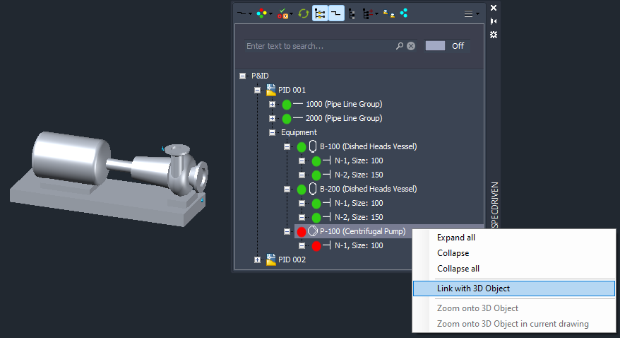
And then the nozzle.
Again the tooltip for confirmation before selecting the nozzle.
And now the pump and its nozzle is linked too.
Next Chapter: Identifying Linked Equipment and Nozzles (P&ID/3D)