|
<< Click to Display Table of Contents >> Flange Class |
  
|
|
<< Click to Display Table of Contents >> Flange Class |
|
If you are using AutoPipe to get flanges (or other end connecting symbols) there is a strict naming scheme you have to follow.
Firstly, there are Right and Left flanges. The class and symbol name must start with L_ or R_ (for Left and Right). For a vertical Pipe Line Segment PlantSpecdriven will of course align the left and right flanges accordingly. Flanges which are supposed to be inserted through the AutoPipe function end with _AutoPipe. In case you want to insert a flange manually in a Pipe Line Segment to show a flange/flange connection the name ends on _Manual. What name you use between the start and end is up to you, but if you have a right flange you need a left flange as well.
Whether you want to have different flange symbols or not is up to you. I the Test Projects we use a Default, a Welding Neck, a Lapped Flange, and more. Having just one flange symbol is ok too. Just have a right and left one and have _AutoPipe at the end. The default flange symbol is also used in case a Pipe Line Segment has no spec and/or size yet, and the Pipe Line Segment is for example connected to a flanged equipment nozzle.
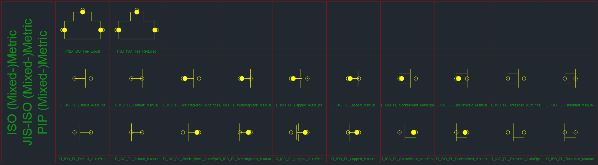
The next image shows the example flange and tee symbols used in the Test Projects. Symbol names and Block names are not required to be the same, but of course it makes it easier to manage the project setup.
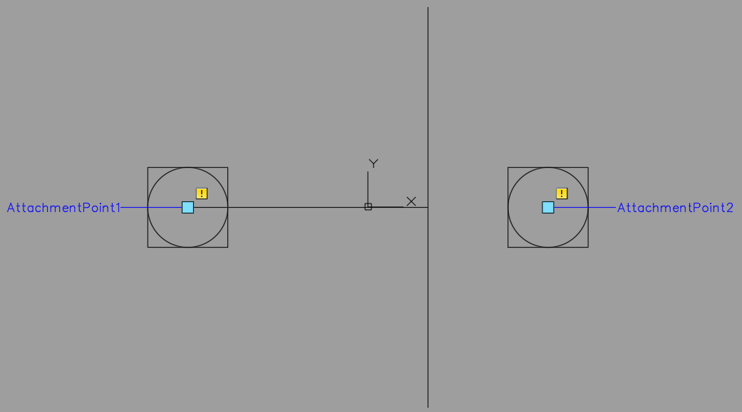
The blocks must have an AutoCAD point at the AttachmentPoints.
For the AutoPipe flanges the insertion point must be in the middle otherwise PlantSpecDriven won't align the flange symbols properly when they need to be rotated. In addition, AttachmentPoint1 has to be on the back side (opposite of the flanged side). AttachmentPoint2 is placed on the flanged side with a gap. This gap will later be the gap you will see either between two flanges or between a flange and a valve.
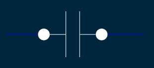
Here you see the left and right Default AutoPipe Flange.
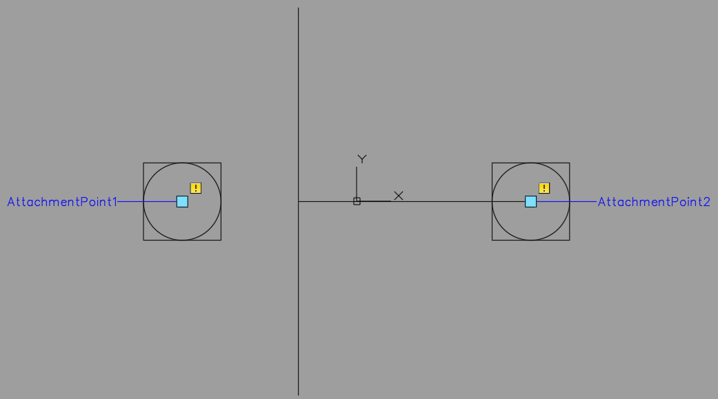
And here the example of the left manual welding neck flange symbol which is typically only used for a flange/flange connection. Make sure, that the center/base point is really in the middle of the block.
You assign the various symbols to the different classes.
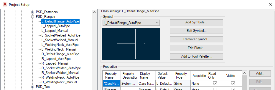
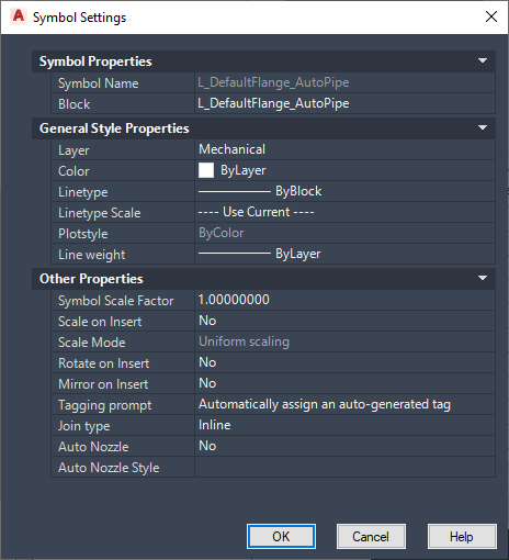
Make sure, that you set the symbol properties according to your needs. This includes the 'Tagging prompt' setting.
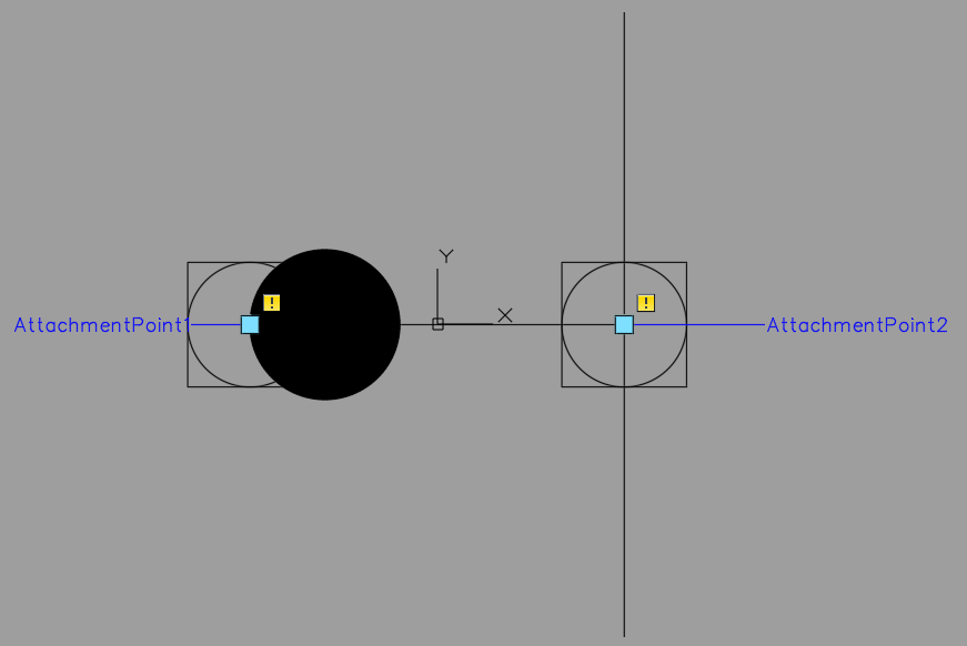
And this is how it will later look when you insert the manual flange symbol and PlantSpecDriven will insert the AutoPipe Flange automatically.
Next Chapter: Fasteners Class