|
<< Click to Display Table of Contents >> Inserting P&ID Relief Valves (3D) |
  
|
|
<< Click to Display Table of Contents >> Inserting P&ID Relief Valves (3D) |
|
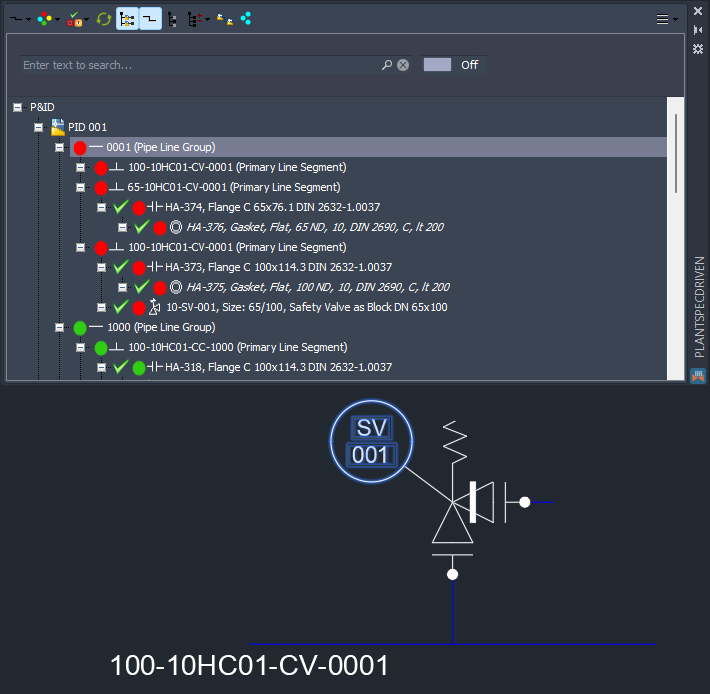
This chapter describes how a P&ID Relief Valve is inserted in 3D.
As with Relief Valves in P&ID, the way to insert a Relief Valve in 3D is also different.
We use the example created under Inserting Relief Valve (P&ID).
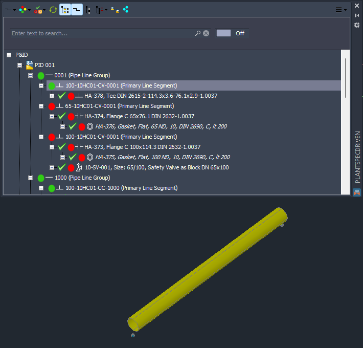
We begin routing the main line segment.
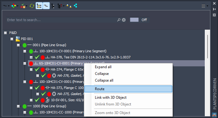
Then we route the branch line segment.
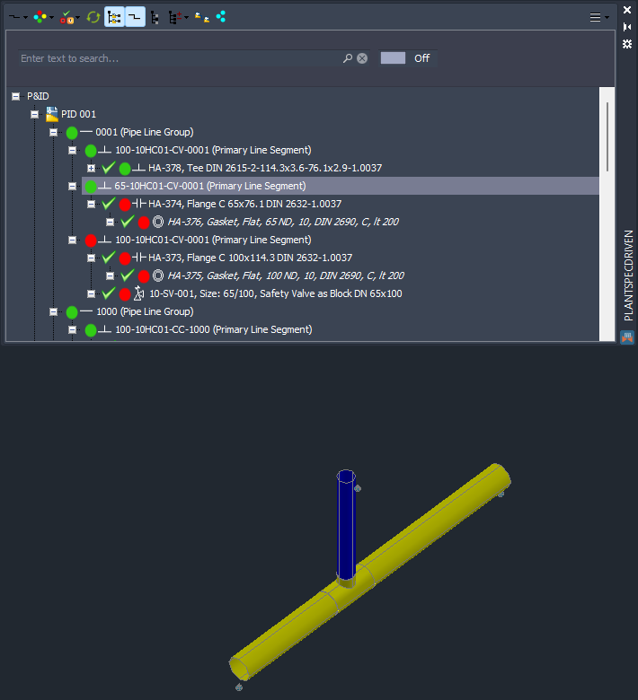
Which results in this.
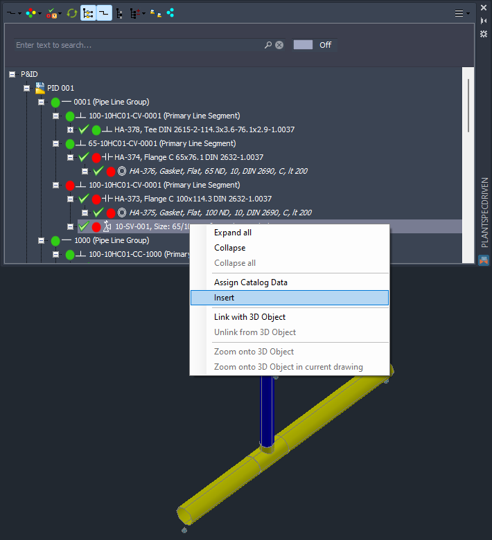
Now we insert the Safety Valve.
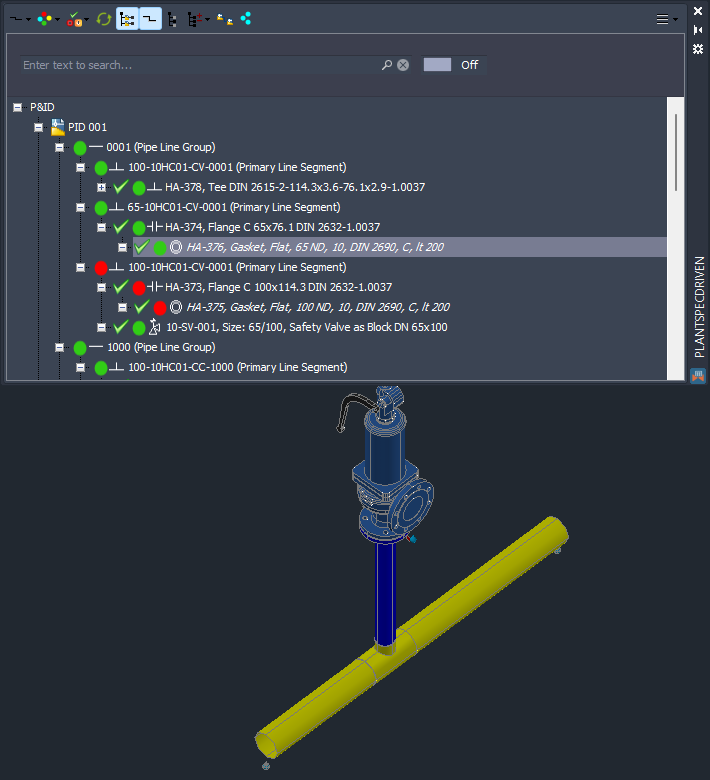
After inserting the valve we see, the not only the valve is linked, but also the flange and gasket from the branch line segment.
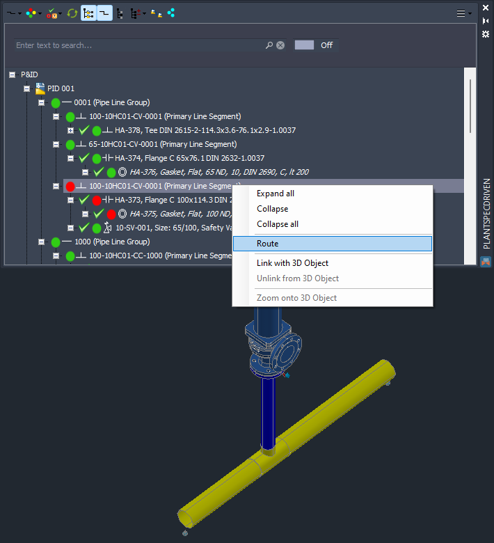
Lastly we route the outlet line segment.
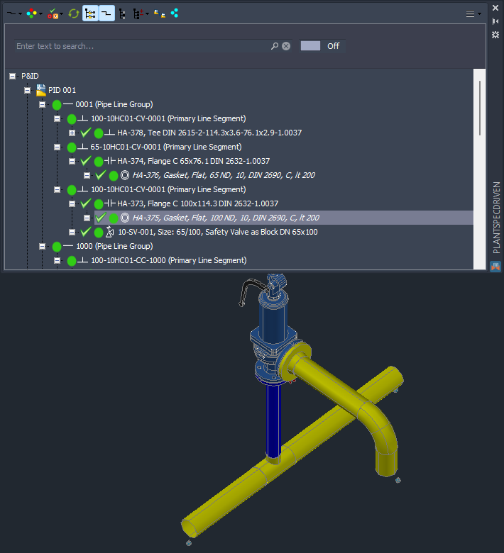
And now everything is linked.
Next Chapter: Inserting Reducers on Nozzles directly (3D)