|
<< Click to Display Table of Contents >> Inserting Relief Valve (P&ID) |
  
|
|
<< Click to Display Table of Contents >> Inserting Relief Valve (P&ID) |
|
This chapter describes how you insert a Relief Valve in P&ID.
Relief Valves behave different than regular Hand Valves, because they have typically two different sizes
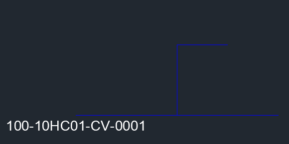
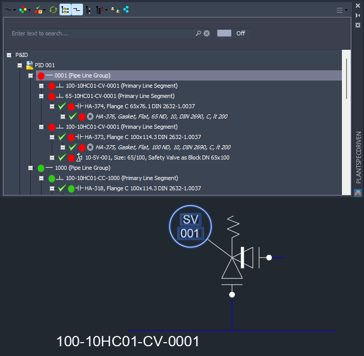
We start with this example where the main line and the branch both have size 100.
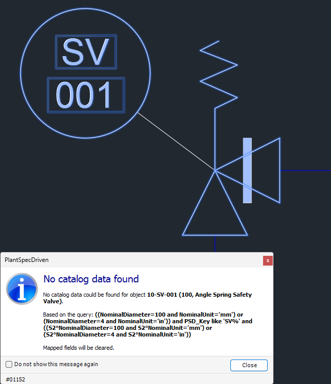
When inserting a Safety Valve we will get the Warning dialog, because in the pipe spec, there is no suitable part with size 100 on both ports.
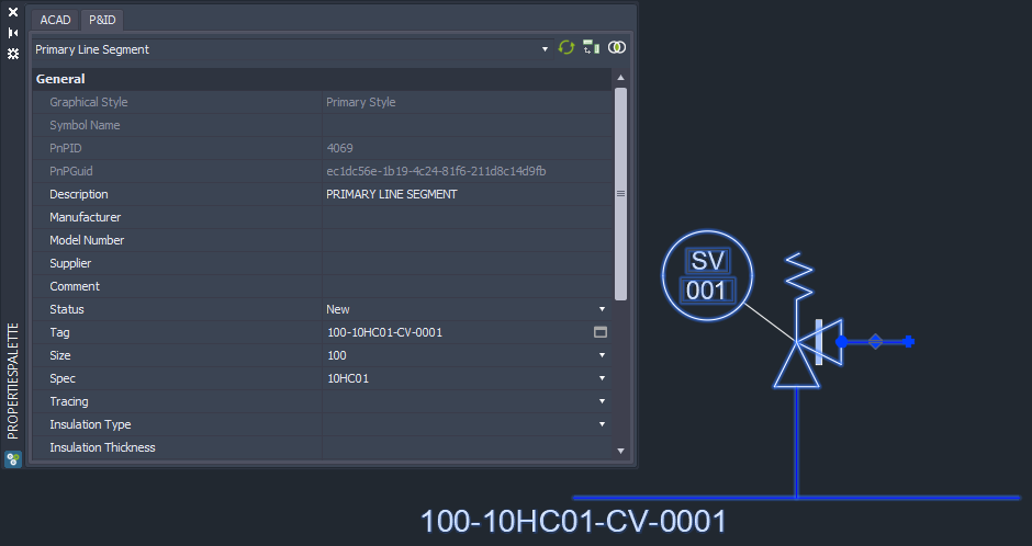
Since Relief Valves are defined as segment breakers, we now have two line line segments. The line segment attached to the outlet side of the valve can keep the size 100.
But the inlet line segment will be changed to 65.
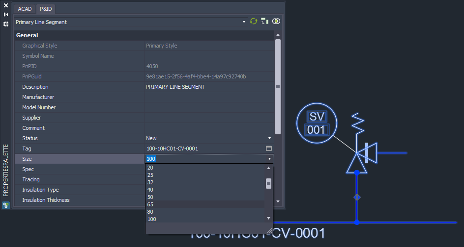
And all of a sudden we see flanges which is already an indicator, that PlantSpecDriven was able to find a part in the Pipe Spec.
We also see, that the flanges and gaskets are in the Structure Tree.
This P&ID example will be converted to 3D under Inserting P&ID Relief Valves (3D).
Next Chapter: Editing Line Segment Properties (P&ID)