|
<< Click to Display Table of Contents >> Drawing a Line Segment (P&ID) |
  
|
|
<< Click to Display Table of Contents >> Drawing a Line Segment (P&ID) |
|
This chapter describes what happens when drawing a Pipe Line Segment in a P&ID Drawing.
If you route a Pipe Line Segment you may see this dialog. This dialog appears if the line connects to an equipment and the equipment has a nozzle with a flanges nozzle.
In this case, you click just on Assign.
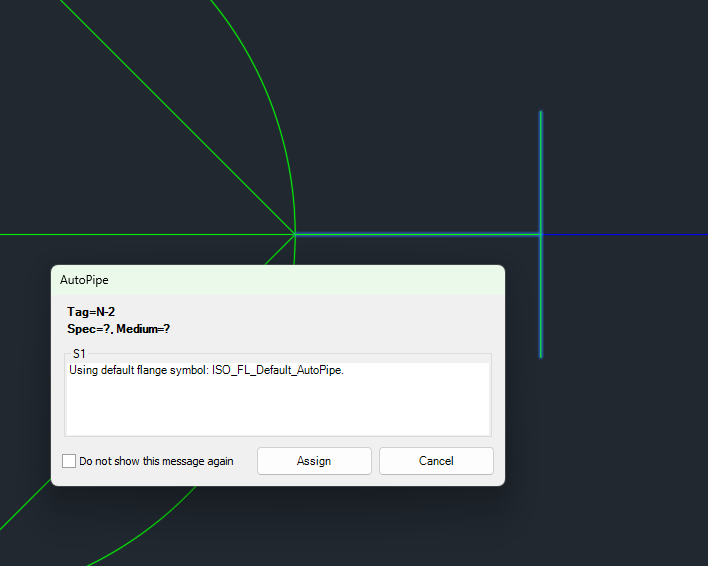
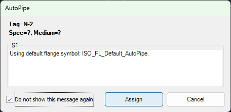
Or you can first select Do not show this message again and then click on Assign. In this case the dialog will not appear anymore.
If you want to get the dialog again, you can enable it under Dialog Preferences.
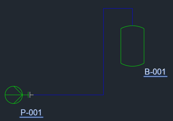
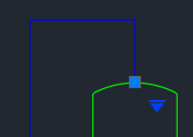
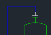
In this example you see the differences between a flanged (pump) and an anonymous (tank) nozzle.
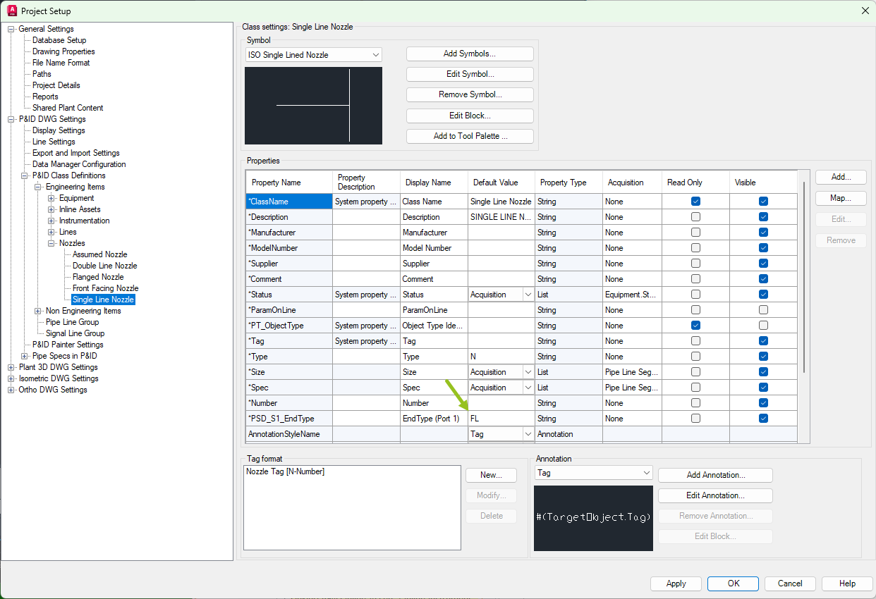
In Project Setup you can see, that the pump will get the ISO Single Lined Nozzle.
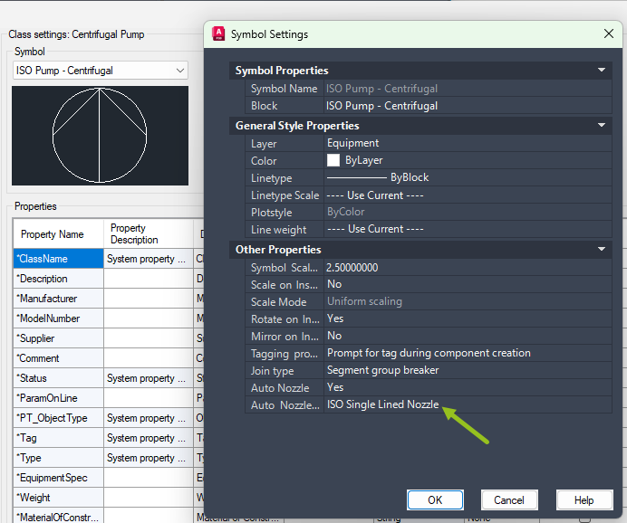
The Nozzle itself has an EndType FL which tells PlantSpecDriven, that this nozzle is flanged and will get a flanges nozzle (see Page 13 - AutoPipe - Flanges).
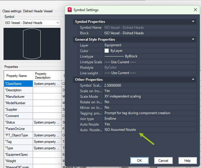
In this example the tank just uses the ISO Assumed Nozzle.
If you select the nozzle...
...and you substitute the nozzle with the ISO Single Lined Nozzle...
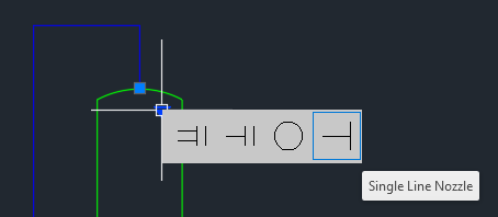
...you will get the Default Flange too.
Next Chapter: Inserting Symbols (P&ID)