|
<< Click to Display Table of Contents >> Page 13 - AutoPipe - Flanges |
  
|
|
<< Click to Display Table of Contents >> Page 13 - AutoPipe - Flanges |
  
|
This page allows you to setup the AutoPipe options of PlantSpecDriven. If you disable the AutoPipe checkbox, then al lthe other settings will be disabled in the user interface. This also applies to the settings on Page 14 - AutoPipe - Fasteners.
By default, nothing is selected.
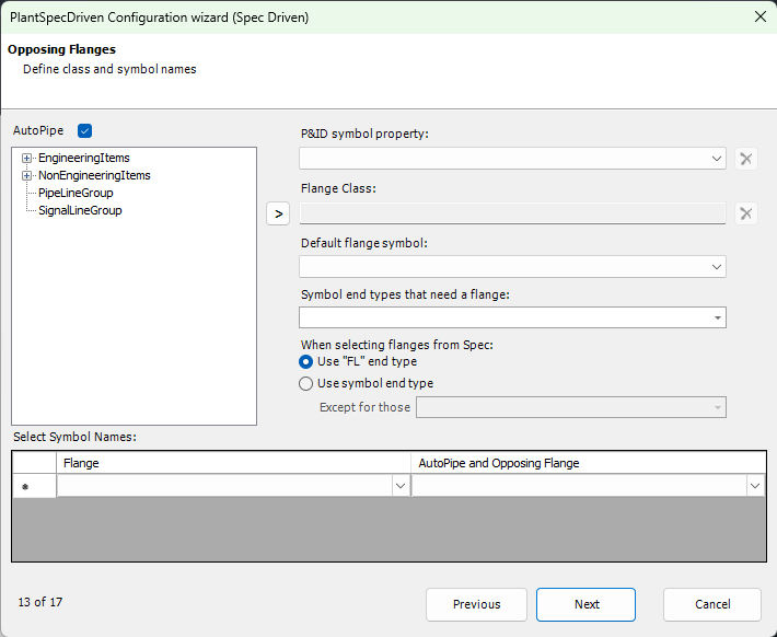
You start by selecting the property which holds the Symbol Name of your P&ID symbols (see Inline Assets Class). If you don't select the property PlantSpecDriven will not be able to substitute the symbols.
Next you select the class under which all your flanges are located. In Test Projects you will find the flanges under the Piping Fittings class. Select the class in the tree and use the right arrow symbol to copy the class to the right.
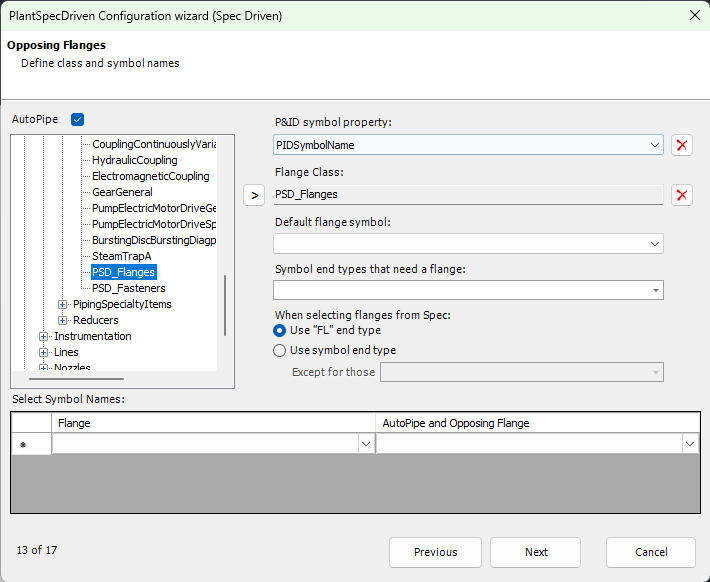
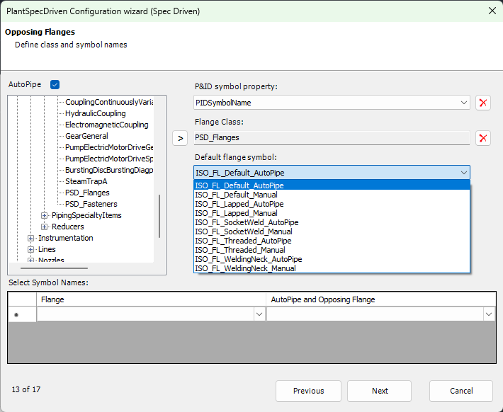
Next you select the flange class which is supposed top be used as the default flange symbol in case there is no spec given in a line segment and therefore PlantSpecDriven doesn't know what spec to look into (see Flange Class).
Next you select the End Types PlantSpecDriven should react on. Typically you will select FL and WF, but you may have other End Codes defined as Flange Like.
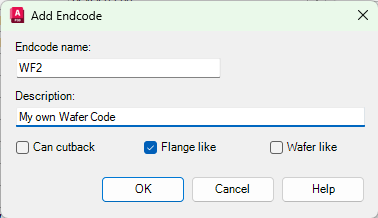
If you use AutoPipe also for other End Types (e.g. TriClamp) you may consider adding other End Types from the list.
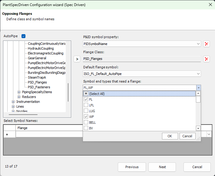
With the settings under When selecting flanges from Spec you define which end type should be used to filter the spec (in addition to the size and probably PSD_Key). If you use PlantSpecDriven for flanges only, then FL should be sufficient, but when using for example something like TriClamps you may have to use other end types as well.
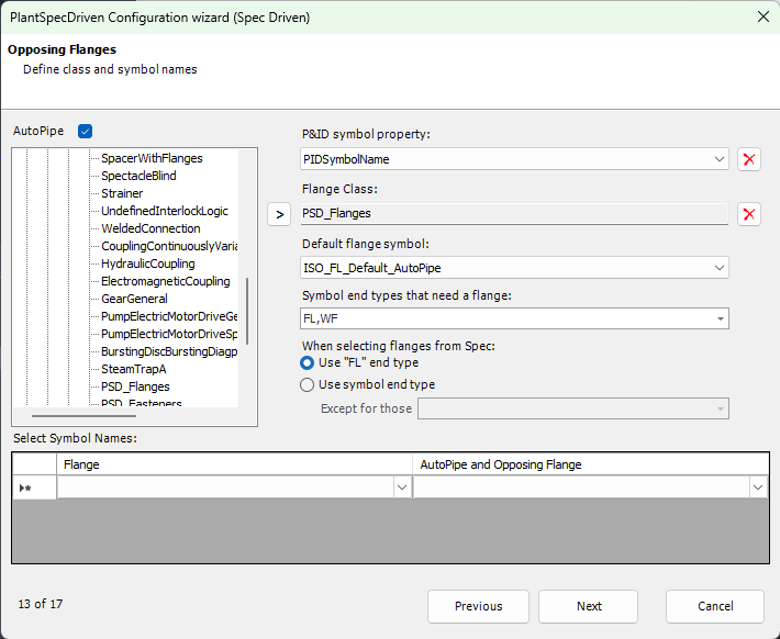
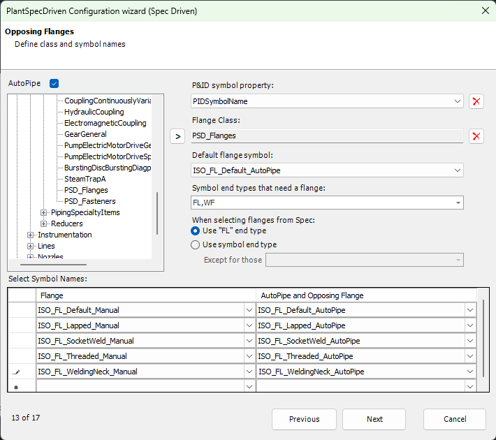
The Select Symbol Names is needed only if you manually insert flanges in a line segment to generate a double flange connection.
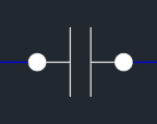
If you don't use this in your P&ID drawings, then you can leave this section blank (see Flange Class). For every Manual flange type you must select the opposing Autopipe flange.
Next Chapter: Page 14 - AutoPipe - Fasteners