|
<< Click to Display Table of Contents >> Inserting Relief Valves |
  
|
|
<< Click to Display Table of Contents >> Inserting Relief Valves |
|
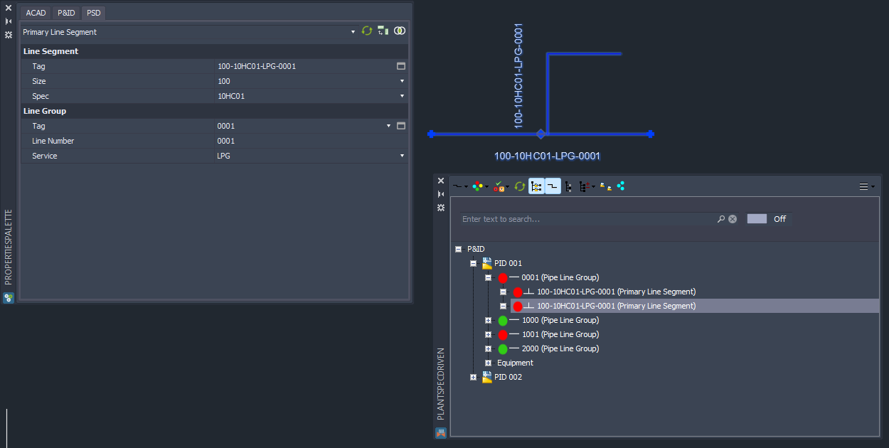
This chapter describes the assigning of pipe spec data to Relief Valve.
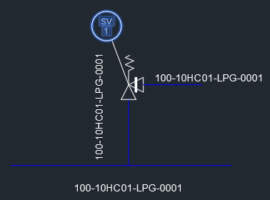
We start with a main line and a branch both with the same size.
Now we insert a Safety Valve This example shows the use of an Angle Valve, but it would also work with a Straight Valve.
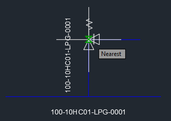
You enter the Tag.
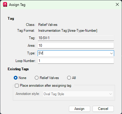
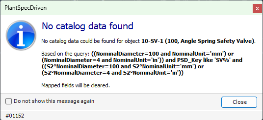
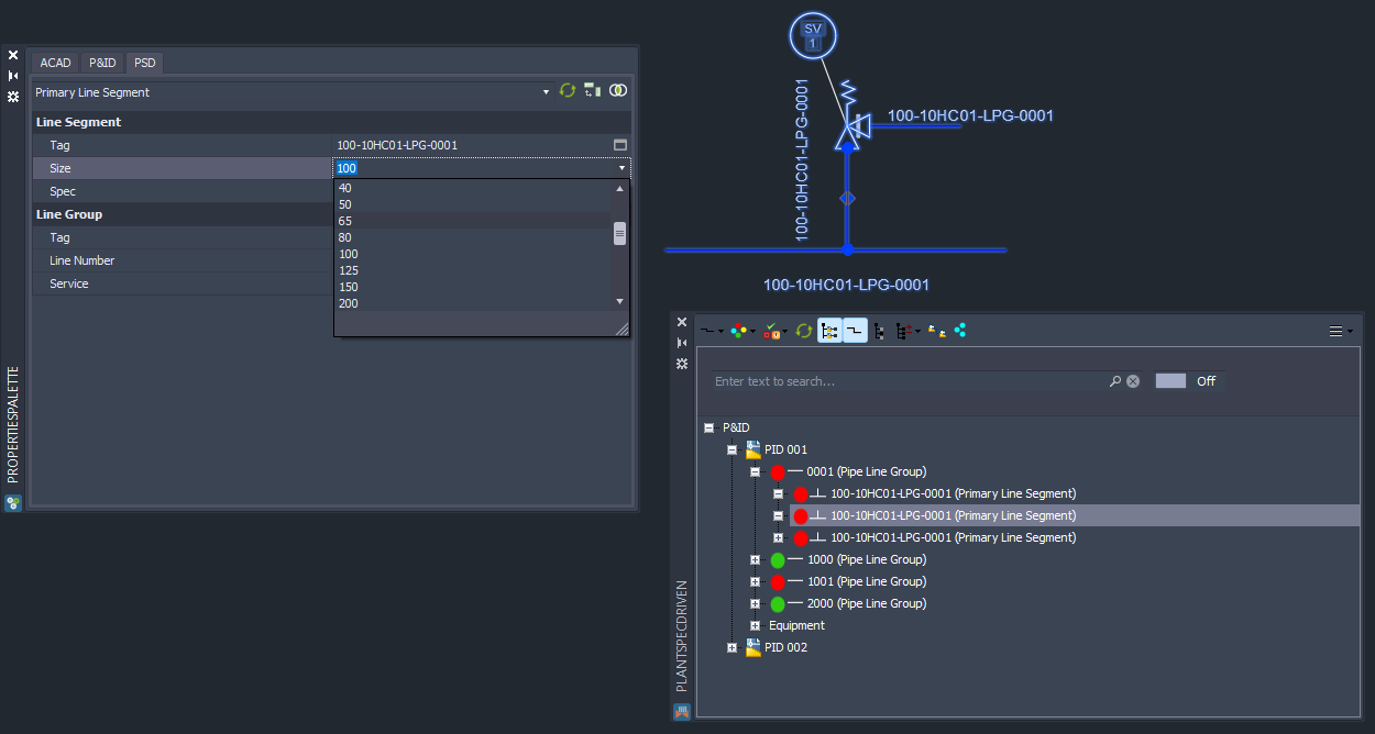
Now we probably get this dialog, because the valve is typically defined as a segment breaker and typically has different sizes on both AttachmentPoints/Ports.
We add a line annotation to the discharge side of the valve so we can see which line segment has what size.
We change the size of the line segment which goes into the safety valve.
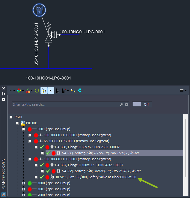
In this example there was just one suitable part in the pipe spec. Since it is a flanges valve, we get flanges on both sides.
In the tree we see, that the valve is appearing under the discharge side of the two line segments. This will become important later when transitioning to 3D (see Inserting P&ID Relief Valves (3D)).
Next Chapter: Updating assigned data on Spec/Size change