|
<< Click to Display Table of Contents >> Routing P&ID Line Segments (3D) |
  
|
|
<< Click to Display Table of Contents >> Routing P&ID Line Segments (3D) |
|
This chapter describes how you route P&ID line segments in 3D.
We use this initial example from Test Projects.
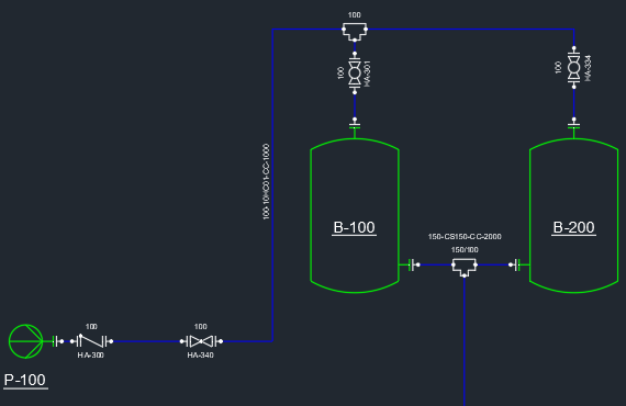
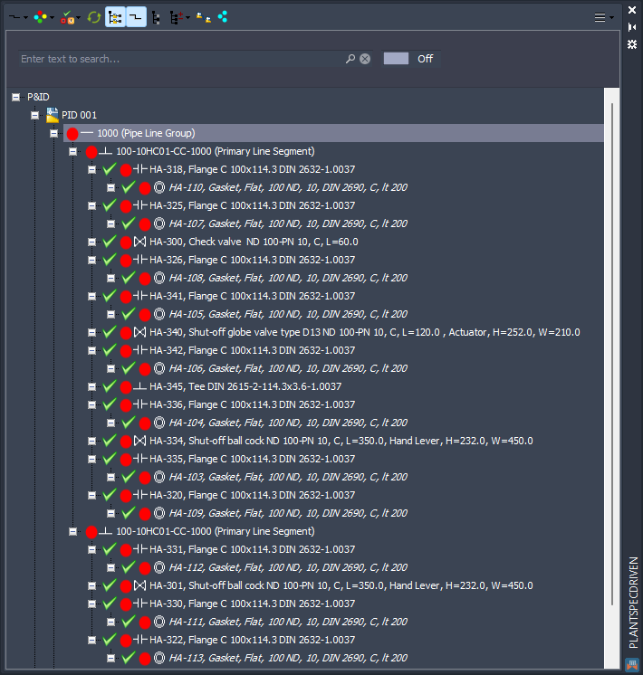
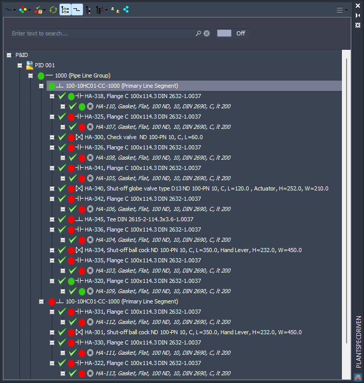
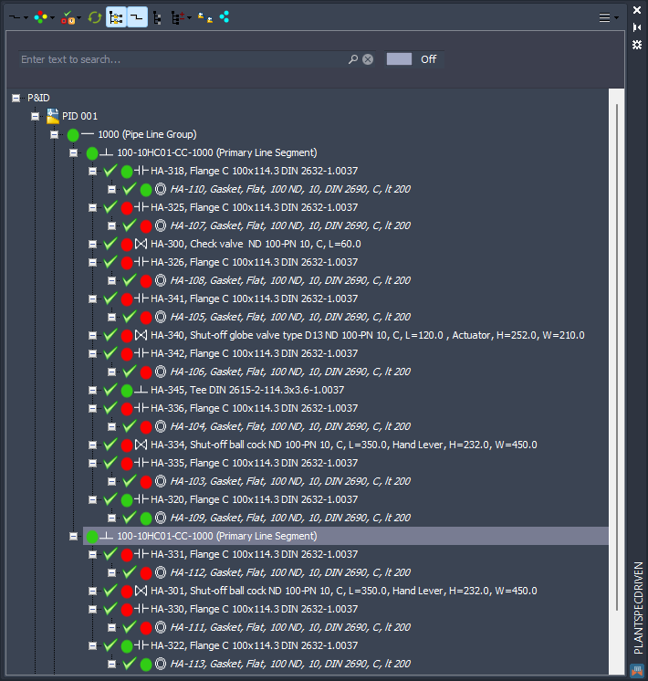
The fully expanded tree from line number 1000 looks like this:
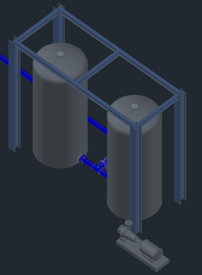
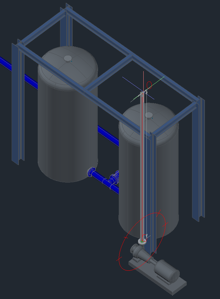
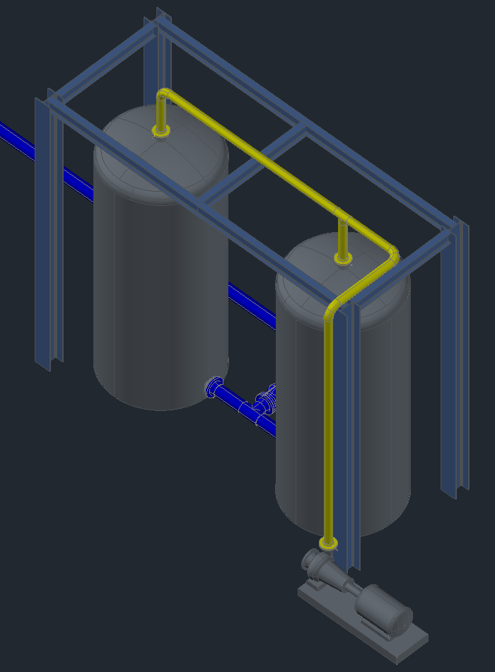
The 3D model looks like this. We have the pump and the two tanks.
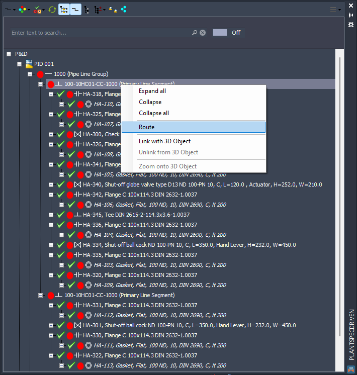
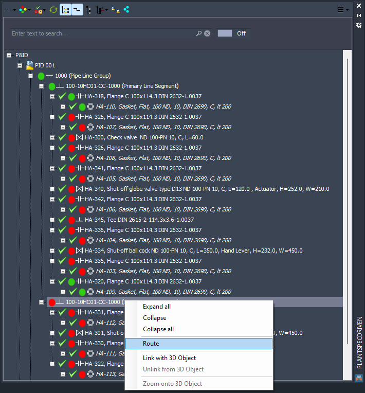
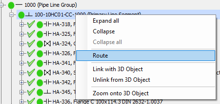
You start the routing by making a right-click on the P&ID line segment you want to route in 3D and select Route.
Remark: During this process PlantSpecDriven may open the involved P&ID drawing in read-only mode. This happens if the P&ID drawing contains flanges or Fasteners.
You start at the pump...
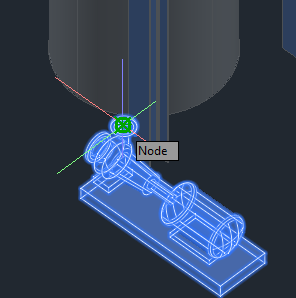
...and start routing.
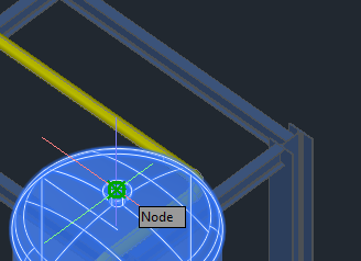
You connect to the top nozzle of the tank.
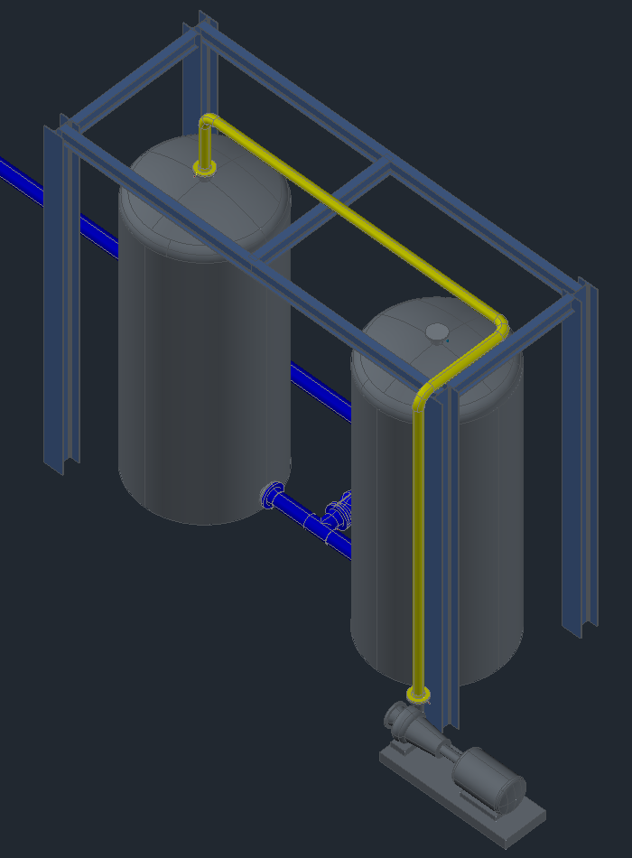
Now that the line is fully connected on both sides it looks like this.
In the Structure Tree you see that the Pipe Line Group and the Pipe Line Segment is green now. This indicates, that the P&ID Pipe Line Group and Pipe Line Segment are linked to their 3D counterparts.
Since Plant 3D doesn't have Line Segments in 3D we use the 3D Pipes and Elbows and link them to the P&ID Line Segments. Details can be found under Linking P&ID Line Segment (3D).
You also see, that the P&ID Flanges and Fasteners are linked.
Next we route the branch line segment.
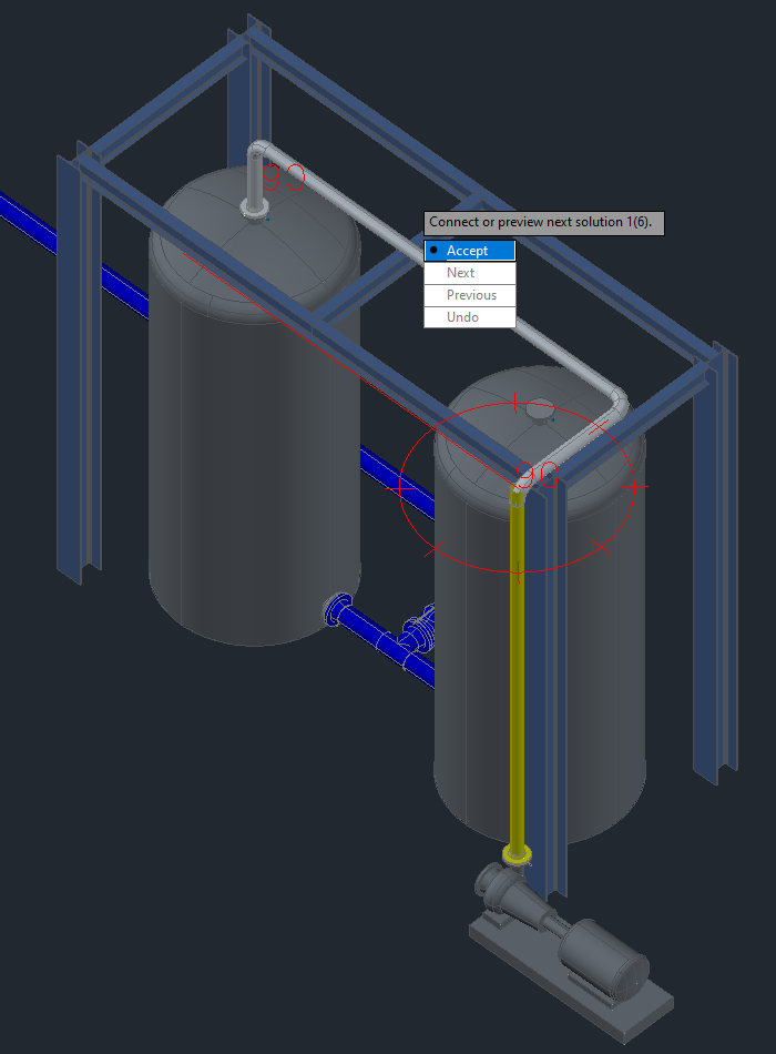
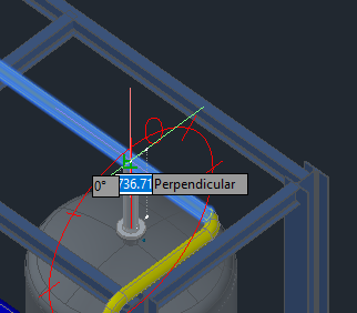
We start at the second tank...
...and route perpendicular to the pipe above the nozzle.
The end result looks like this:
In the Structure Tree you see that the P&ID branch Line Segment is linked and the Flange and Fastener attached to the nozzle.
You may also recognize, that the P&ID Tee is linked automatically to the 3D tee.
Remark:
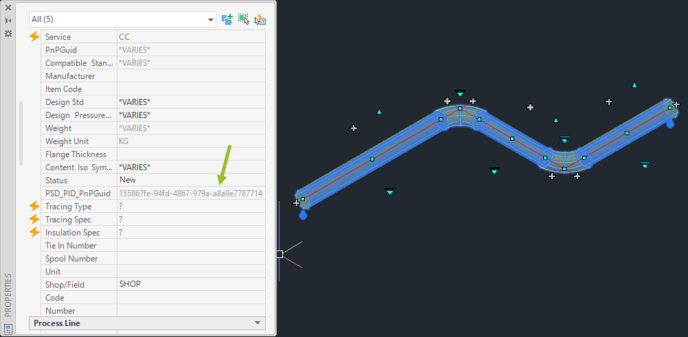
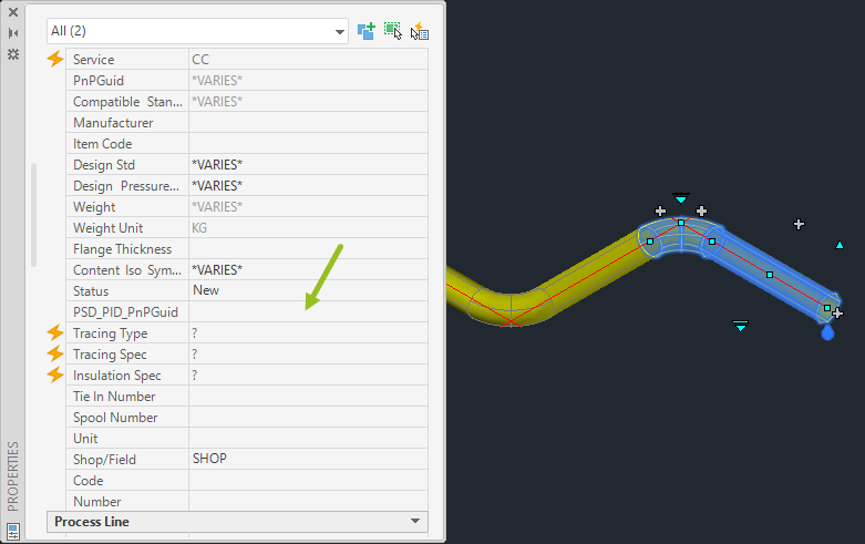
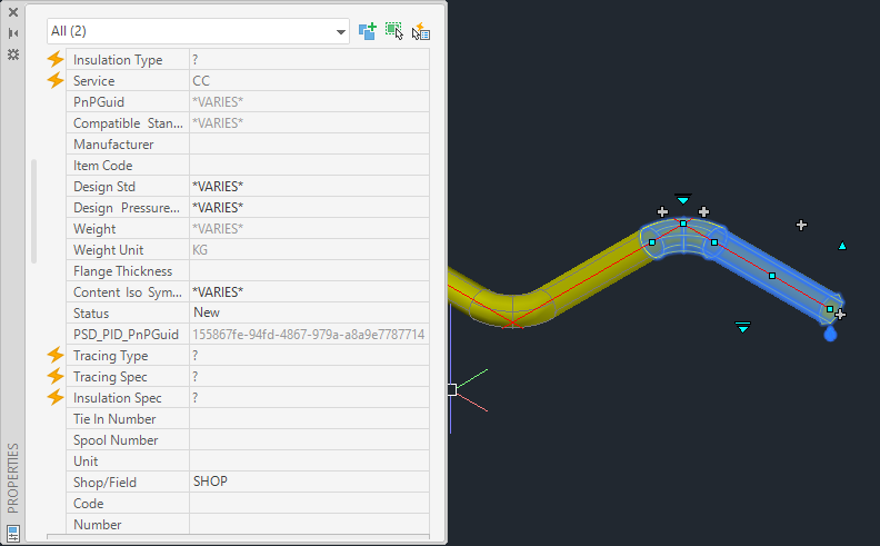
When routing a line segment the pipes and elbows will get the PnPGUID of the P&ID Line Segment in the property. The property is defined at the top of Page 15 - P&ID <--> 3D Mapping.
However, when you use the continuous grips to add more routing to the beginning or end of the 3D pipe line...
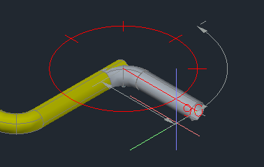
... the PnPGUID will NOT be filled out.
You can avoid this by using the Route function again from the tree (instead of using the Continuous grips)
or you use the Link with 3D Object function
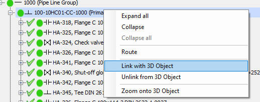
and select the added pipes and elbows. You can also select parts which already have the PnPGUID in them.
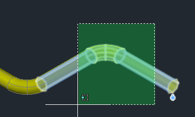
If you check now, you will see, that the added pipes and elbows will also show the PnPGUID.
Next Chapter: Inserting P&ID Inline Assets / Inline Assets (3D)