|
<< Click to Display Table of Contents >> Inserting P&ID Inline Assets & Inline Instruments (3D)) |
  
|
|
<< Click to Display Table of Contents >> Inserting P&ID Inline Assets & Inline Instruments (3D)) |
|
This chapter describes how to insert P&ID Inline Assets or Inline Instruments in 3D.
If you use P&ID Flanges or Fasteners you don't need to insert them separately. Unless you have a flange/flange connection (see Inserting Flange/Flange connections).
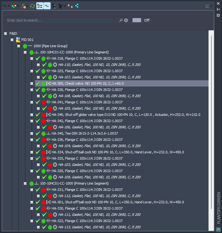
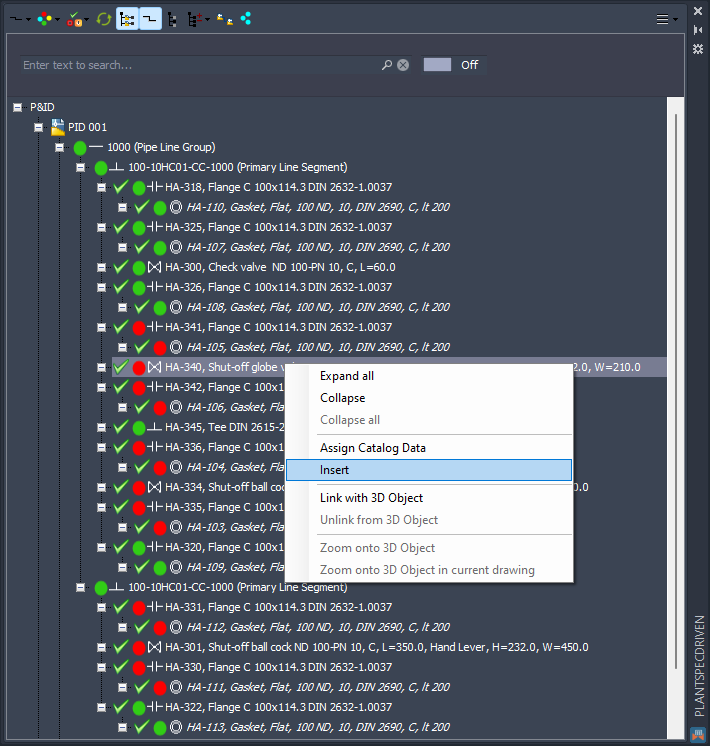
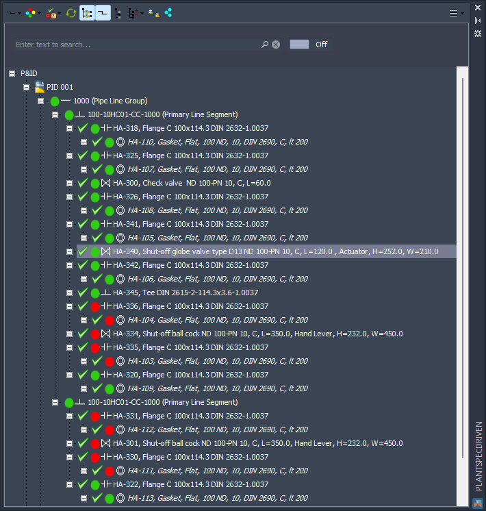
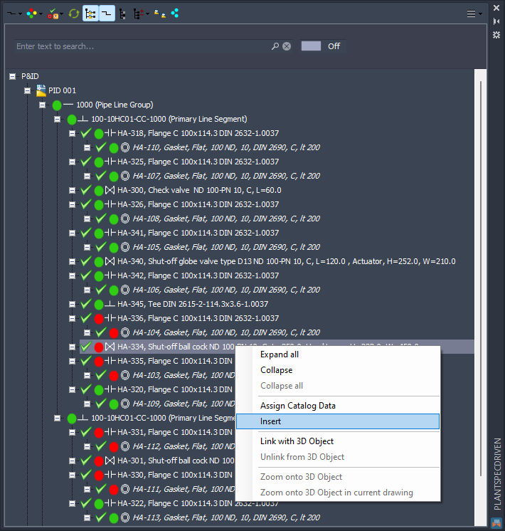
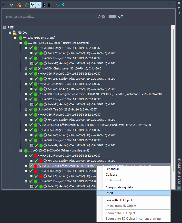
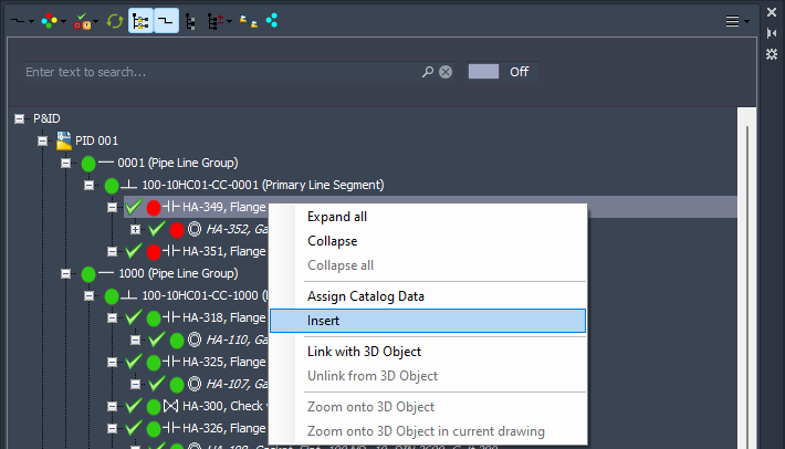
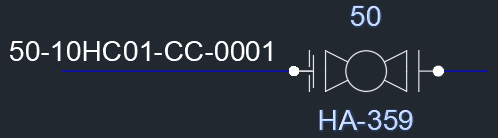
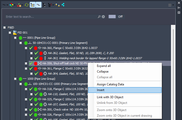
Continuing the example from the previous chapter we start inserting the Hand Valves or Inline Assets from the Structure tree. For this we use Insert from the context menu. Make sure, that the green check sign is shown. Only then a part is assigned to the P&ID symbol.
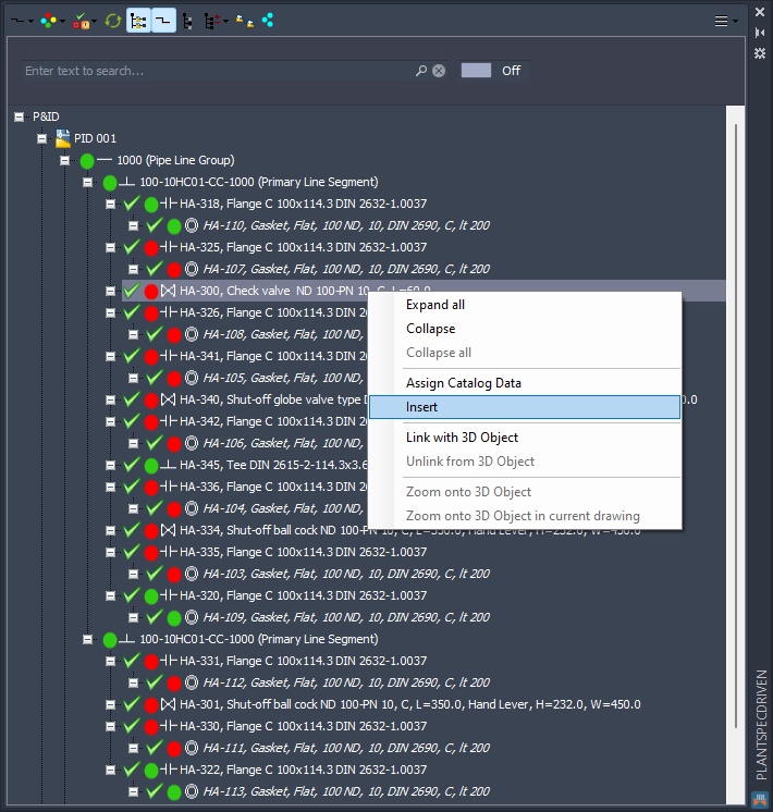
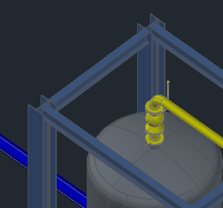
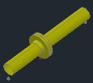
You now have the correct symbol on your mouse.
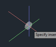
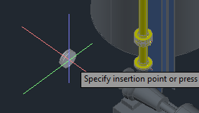
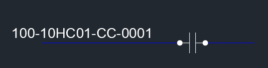
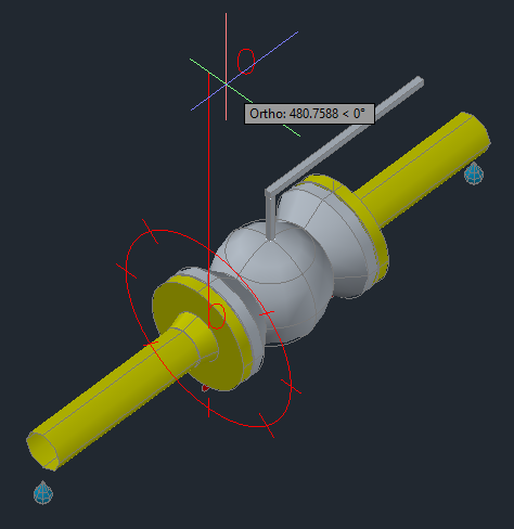
From now on the process doesn't differ from using the Spec Viewer. You insert the valve into the pipe.
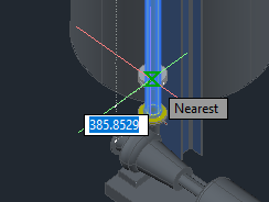
After rotating it Plant 3D will automatically insert flanges and Fasteners depending on your Joint Settings in Project Setup.
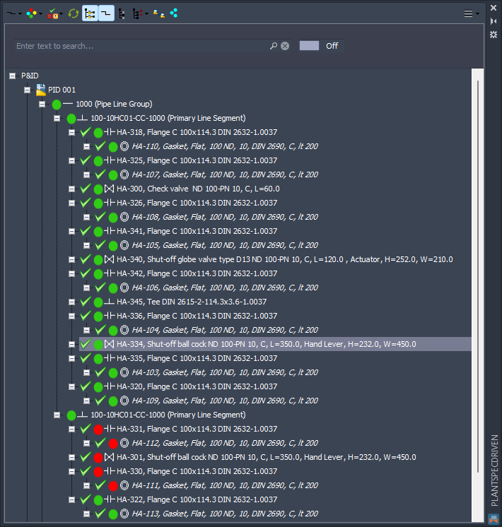
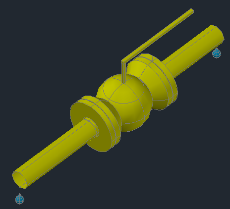
When you terminate the process by using the ESC key...
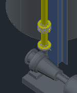
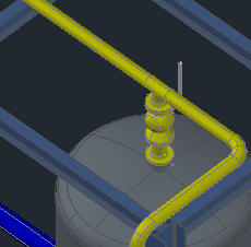
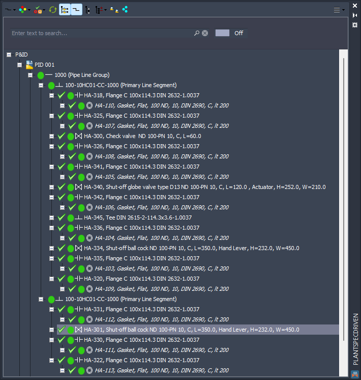
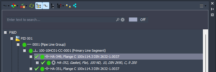
PlantSpecDriven will link the valve, flanges, and Fasteners automatically. As can be seen at the green dot.
We continue with the next valve.
And insert it too.
Remark: Although the Structure Tree shows the P&ID symbols in order of the flow direction (unless deactivated. See Flow Sort Order) it is not mandatory to insert the valves from the beginning of the pipe and work your way to the end. You can insert the last valve first or in what ever order.
Remark: Although the P&ID symbols are in flow direction, PlantSpecDriven doesn't check if the 3D valves are inserted in the same order.
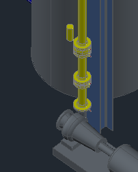
Again, everything in gets linked.
No the last valve of this line segment.
We insert it at the tank.
And now everything is green and therefore linked and consistent.
Finally, the valve of the branch to the second tank.
Insert it at the Tee.
And now the second line segment is linked too.
Next is an example created in Inserting Symbols (P&ID).
Here the left flange is a Manual flange and the right one is an AutoPipe flanges (like all the other flanges used previously).
If you try to insert an AutoPipe flange you will recognize, that the Insert option is disabled.
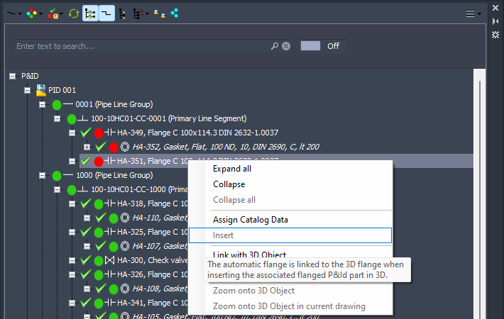
But when using using the context menu on the Manual flange Insert is available.
After inserting the Manual flange Plant 3D will insert the opposing flange automatically (based on the Joint Settings in Project Setup and then PlantSpecDriven will automatically link this 3D flange to the P&ID AutoPipe flange.
In the Structure Tree you will now see, that both flanges and the one gasket are linked.
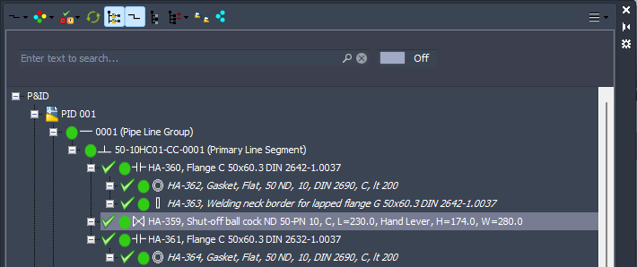
This is an example created in Inserting Symbols (P&ID).
Here we have a lapped flange on the left side and a welding neck flange on the right.
In the Structure Tree we see, that the lapped flange not only has a gasket, but also a welding neck border (StubEnd).
We insert valve as usual.
After inserting the valve into the pipe we see, that we have a welding neck flange on both sides. This stems from the Joint Settings in Project Setup.
After finishing the insertion and using ESC to terminate the process PlantSpecDriven will replace the left welding neck flange with a lapped flange.
And as always will link the valve, the flanges, and the fasteners automatically.
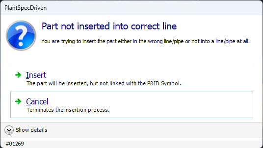
When inserting a P&ID Symbol on the wrong line or on no line/pipe at all the following option dialog appears:
When you click on Insert the part will be inserted in 3D, but not linked. With Cancel the part will be removed again.
Next Chapter: Inserting P&ID Reducers and Tees (3D)